Photoactivated chemical bleaching of dyes

a technology of photoactivated chemicals and dyes, applied in the field of photoactivated chemical bleaching of dyes, can solve the problems of increased signal-to-noise ratio, and achieve the effect of rapid signal cycling

Active Publication Date: 2013-06-27
LEICA MICROSYSTEMS CMS GMBH
View PDF2 Cites 17 Cited by
  • Summary
  • Abstract
  • Description
  • Claims
  • Application Information

AI Technical Summary

Benefits of technology

[0054]In some embodiments, the method allows rapid signal cycling without significantly modifying the components of the biological sample that are different from the probe.

Problems solved by technology

In some embodiments, the disclosed methods also may be characterized by the absence of residual fluorescence even in high expression targets resulting, e.g., in increased signal-to-noise ratio.

Method used


Image

  • Photoactivated chemical bleaching of dyes
  • Photoactivated chemical bleaching of dyes
  • Photoactivated chemical bleaching of dyes

Examples


example 1

Photoactivated Chemical Bleaching of Cyanine Dyes: Dose Response

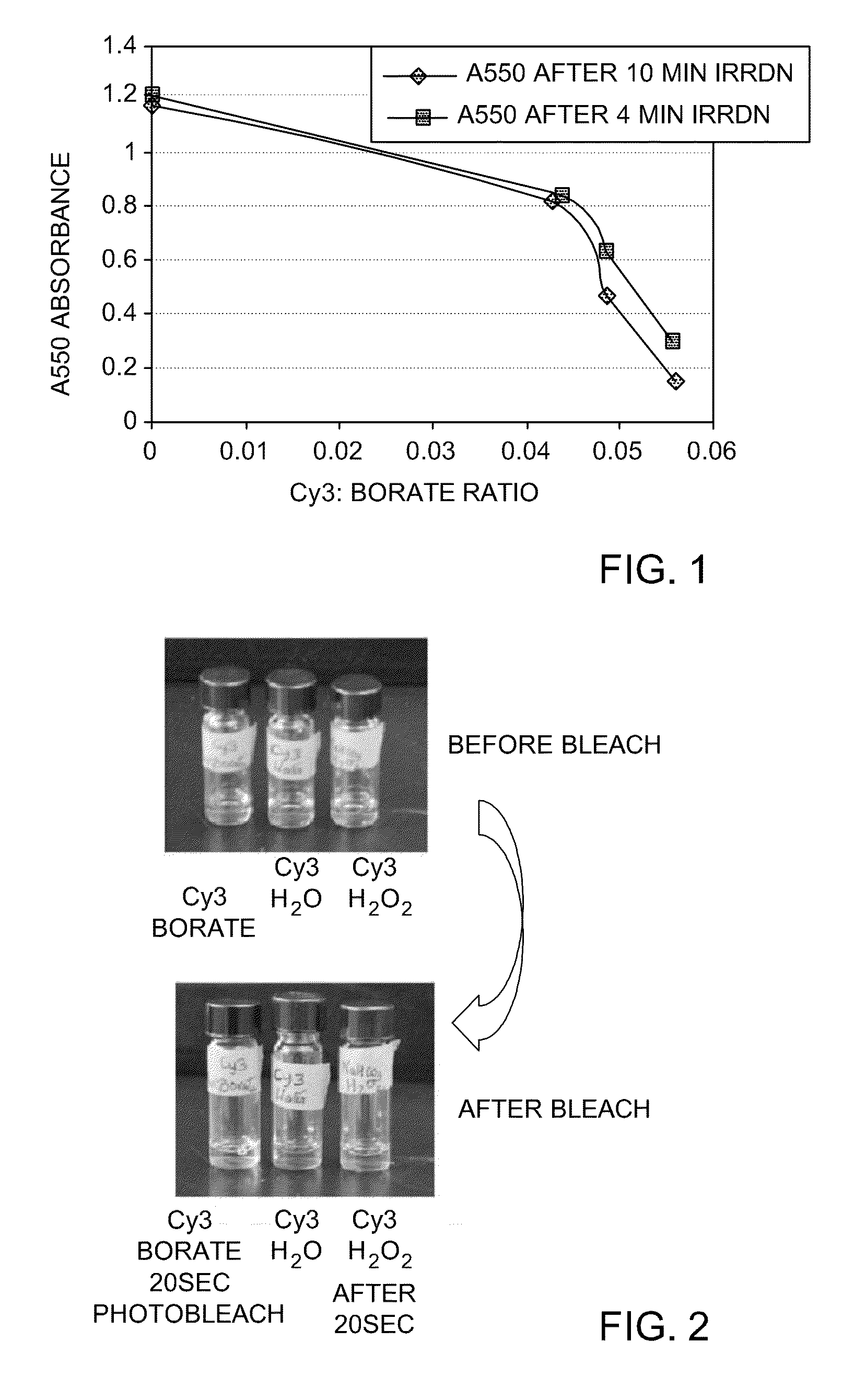
[0277]To a solution of Cy3 in PBS, 2-60 equivalents of triphenylbutyl borate lithium salt were added, and the solution was irradiated for 4 minutes or for 10 minutes. Absorbance at 550 nm was measured to monitor photoactivated chemical bleaching, and the results were plotted, as is shown in FIG. 1. The solid line with squares represents A550 absorbance after Cy3 dye was irradiated for 4 minutes in the presence of different concentrations of triphenylbutyl borate. The solid line with diamonds represents A550 absorbance after Cy3 dye was irradiated for 10 minutes in the presence of different concentrations of triphenylbutyl borate. The results demonstrate that the extent of Cy3 bleaching increases with increasing concentration of the borate salt.

example 2

Comparison of Cy3 Bleaching by Photoreaction and Thermal Oxidation

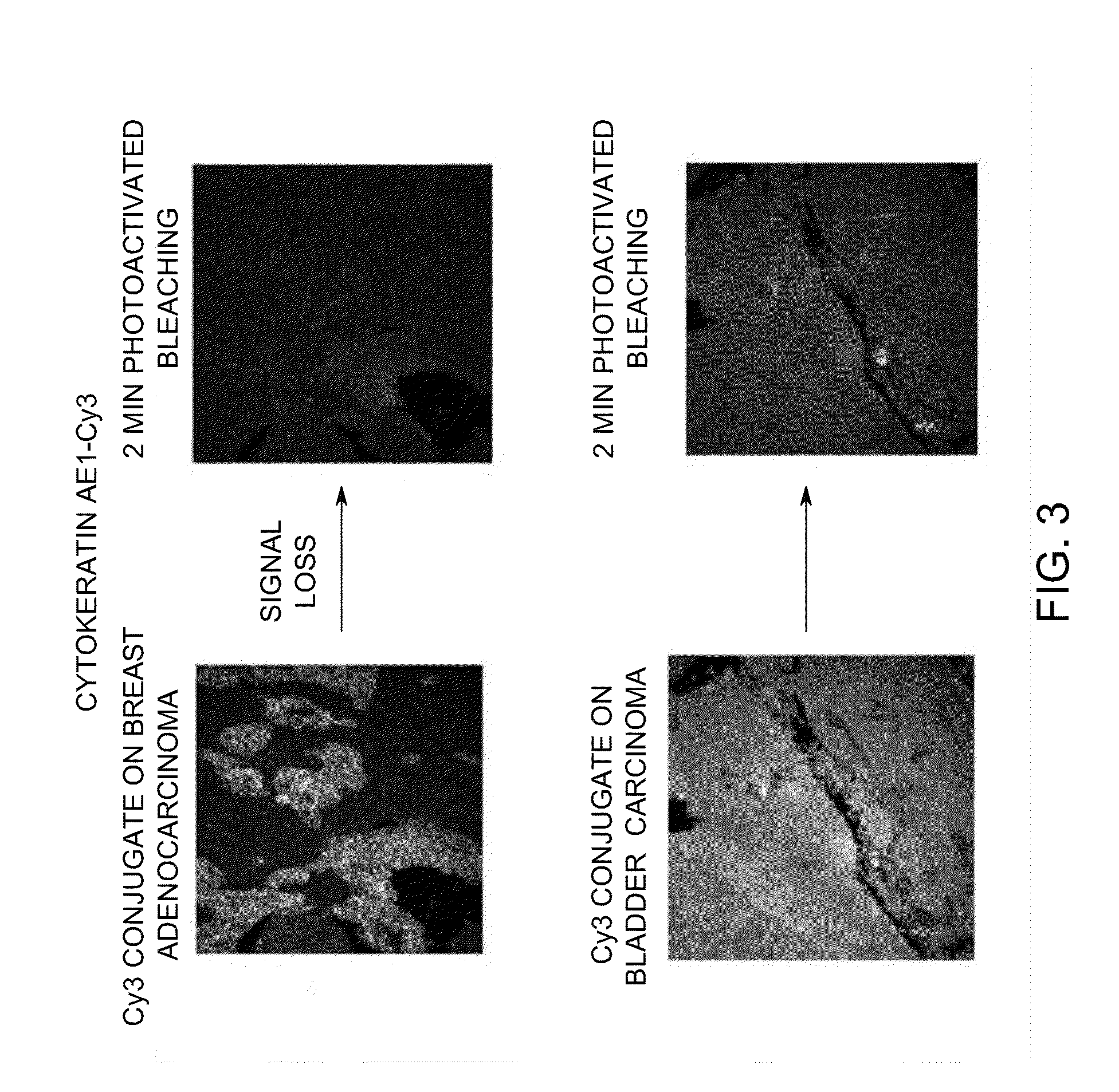
[0278]Three methods for bleaching Cy3 were compared. For the photoactivated chemical bleaching reaction, Cy3 was mixed with triphenylbutylborate lithium salt and irradiated for 20 seconds. For the thermal oxidation reaction, Cy3 was mixed with basic hydrogen peroxide and incubated for 20 seconds. For the control reaction, Cy3 was incubated with water for 20 seconds. The color of the Cy3 solution in all three reactions was compared before and after each incubation and / or reaction. Shown in FIG. 2 is the grayscale image of the vials containing the thermal oxidation reaction, the photoactivated chemical bleaching reaction and the control reaction before and after completion of bleaching. The control reaction does not change its dark pink color (vial shown in the center). The color of the thermal oxidation reaction changes from dark pink to light pink after 20 seconds of thermal oxidation (vial shown on the right). The ph...

example 3

Photoactivated Chemical Bleaching of Cy3 and Cy5 in Tissues

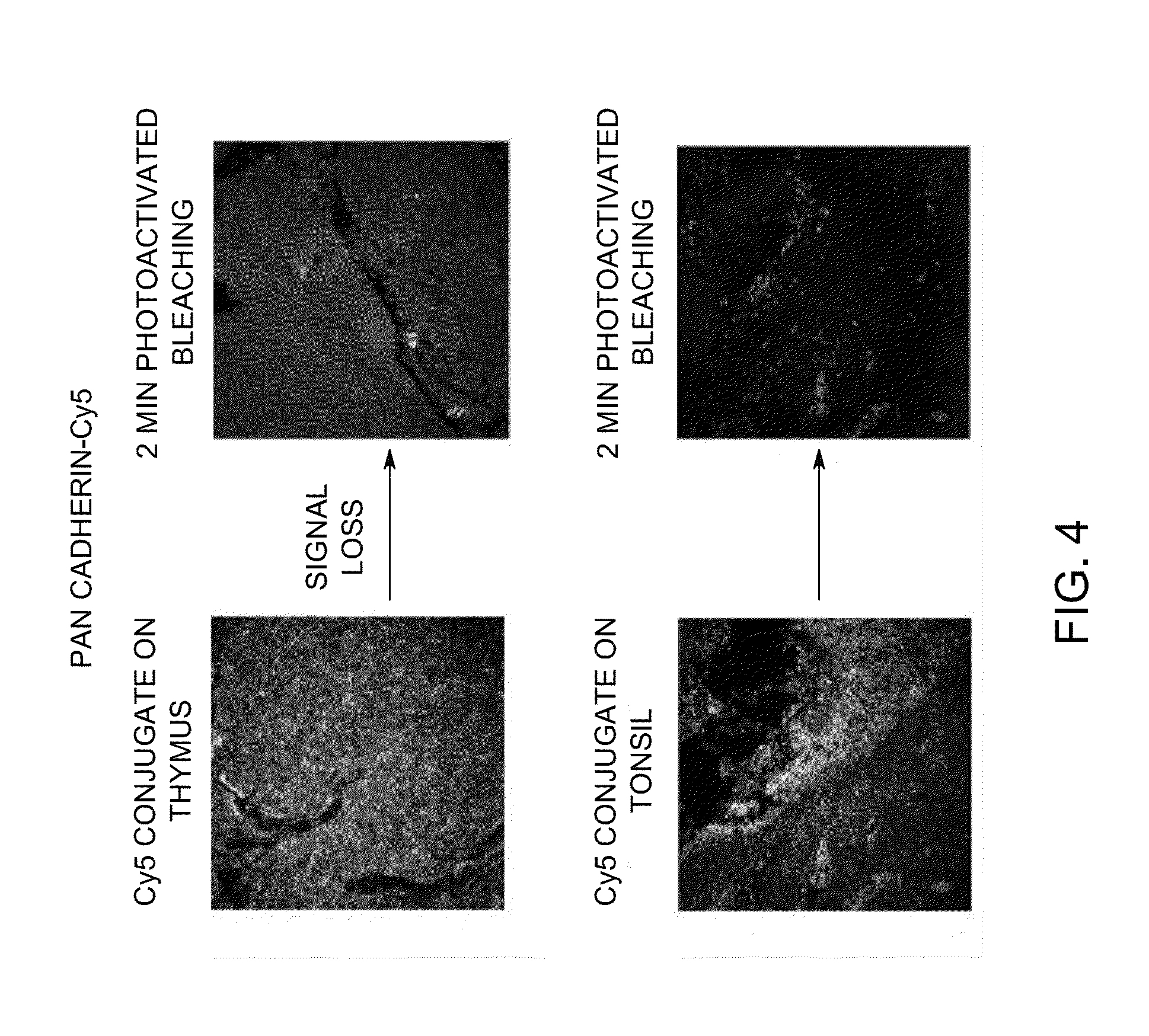
[0279]Tissue Microarrays (TMA, Pantomics Catalog No. MTU541C) were stained with Cy3-conjugated cytokeratin and Cy5-conjugated pan-cadherin. Photoactivated chemical bleaching of the Cy3 and Cy5 was accomplished by incubating stained TMAs with triphenylbutylborate lithium salt and irradiation for 2 minutes. Images were taken on the Olympus Microscope before and after bleaching. Images of samples stained with Cy3-conjugated cytokeratin before and after bleaching are shown in FIG. 3. Images of samples stained with Cy3-conjugated cytokeratin before and after bleaching are shown in FIG. 4. This data demonstrates that photoactivated chemical bleaching effectively destroys Cy3 and Cy5 signals in stained tissues.


PUM

PropertyMeasurementUnit
temperatureaaaaaaaaaa
wavelengthaaaaaaaaaa
temperatureaaaaaaaaaa

Abstract

Methods comprising the use of photoactivated chemical bleaching for detecting multiple targets in a biological sample are provided. The methods include the steps of providing a biological sample containing multiple targets, binding at least one probe to one or more target present in the sample, and observing a signal from the probe. The method further includes the steps of contacting the sample comprising the bound probe with an electron transfer reagent and irradiating the sample, thereby initiating a photoreaction that substantially inactivates the probe by photoactivated chemical bleaching. The method further includes the steps of binding at least one probe to one or more target present in the sample, and observing a signal from the probe. The process of binding, observing and bleaching may be iteratively repeated.

Description

BACKGROUND[0001]Various methods may be used in biology and in medicine to observe different targets in a biological sample. For example, analysis of proteins in histological sections and other cytological preparations may be performed using the techniques of histochemistry, immunohistochemistry (IHC), or immunofluorescence. Analysis of proteins in biological samples may also be performed using solid-state immunoassays, for example, using the techniques of western blots, or using cell-based assays that can be performed, for example, by using flow cytometry.[0002]Many of the current techniques may detect only a few targets at one time (such as IHC or fluorescence-based Western blots where number of targets detectable is limited by the fluorescence-based detection system) in a single sample. Further analysis of targets may require use of additional biological samples from the source, limiting the ability to determine relative characteristics of the targets such as the presence, absence...

Claims


Application Information

Patent Timeline
Patent Type & Authority Applications(United States)
IPC IPC(8): C40B30/04G01N21/64
CPCG01N21/64G01N33/582G01N21/6428G01N33/52
Inventor NATARAJAN, ARUNKUMARSOOD, ANUPKAANUMALLE, LAKSHMI SIREESHACHAN, KWOK PONG
Owner LEICA MICROSYSTEMS CMS GMBH
Why Eureka
Try Eureka