Composite gusset filler and method of manufacture of said composite gusset filler

a composite gusset and filler technology, applied in the field of composite gusset filler, to achieve the effect of reducing structural mass, optimizing section shapes, and increasing strength and structural integrity of skin-stiffener transition

Inactive Publication Date: 2013-07-04
AIRBUS HELICOPTERS DEUT GMBH
View PDF6 Cites 10 Cited by
  • Summary
  • Abstract
  • Description
  • Claims
  • Application Information

AI Technical Summary

Benefits of technology

[0012]The inventive composite gusset filler will support any advantageous gusset section geometry, e.g. optimized section shapes. As a consequence of the advantages provided by the invention results an increase in strength and structural integrity of the skin-stiffener transition allowing exploitation in a reduction of structural mass, i.e. frozen margin of safety. Structural integrity of the CFRP parts may also be increased by homogeneous or specially tailored fiber orientations. For the purposes of the invention the term “yarn” is used with the meaning of fiber.
[0013]The inventive composite gusset filler material itself is manufacturing friendly and easy to handle. Since scrap material can be used for the inventive composite gusset filler material disposal costs could be saved as well.
[0014]According to a preferred embodiment of the invention the raw material for the inventive composite gusset filler is stored with a random fiber orientation.
[0015]According to a further preferred embodiment of the invention the quasi-homogeneous raw material is provided with sufficient single yarn or roving elements oriented according to the main load direction in the area of the inventive composite gusset filler. The single yarn or roving elements oriented according to the main load direction allow improved bearing capacity of the inventive composite gusset filler.
[0016]According to a further preferred embodiment of the invention the fiber volume content of the inventive composite gusset filler is 40% to 60%, preferably about 50%.
[0017]According to a further preferred embodiment of the invention an endless extrusion profile of dry fibers is provided for sufficient dimensional stability during preform manufacturing, injection and curing of the composite. In addition to that the extrusion profile is easy to bend and / or to adapt to curvatures as well as easy to integrate into any dry fiber preform assembly.

Problems solved by technology

Since cut-off material is used for the inventive composite gusset filler the raw material costs only reflect the process costs, such as trimming, etc.

Method used


Image

  • Composite gusset filler and method of manufacture of said composite gusset filler
  • Composite gusset filler and method of manufacture of said composite gusset filler

Examples


Embodiment Construction

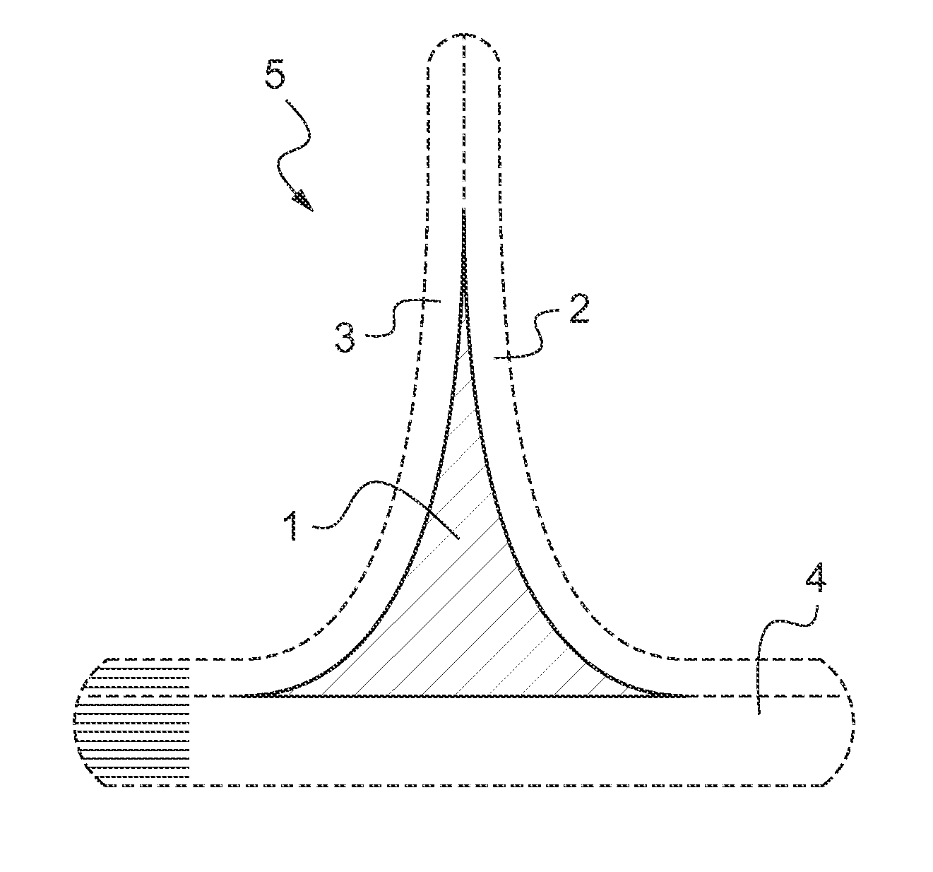
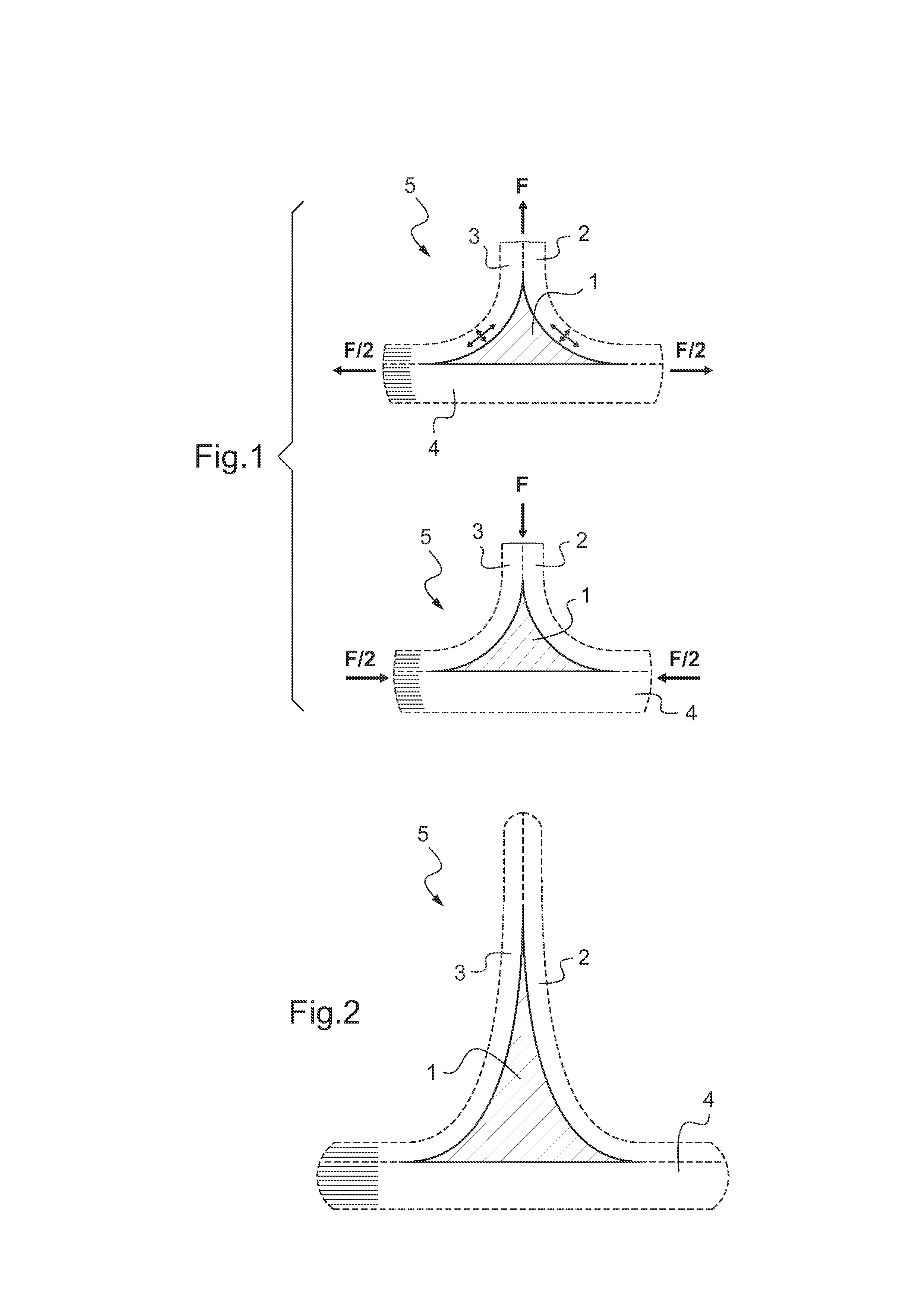
[0027]As shown in FIG. 1 a composite gusset filler 1 for a semi-finished skin-stiffener transition 5 is encompassed by two C-shaped preforms made from fiber-reinforced fabric plies 2, 3 of a semi-finished part for a skin-stiffener transition 5 of an aircraft structure (not shown). The two C-shaped preforms 2, 3 adhere to a skin 4 of the skin-stiffener transition 5. The semi-finished gusset filler 1 is used to create preforms for resin-injected CFRP parts. Preform means the fiber architecture of a CFRP part glued and compacted.

[0028]Each of the two C-shaped preformed fiber-reinforced fabric plies 2, 3 are conceived as a laminate ply stacking.

[0029]If a tensile load F is applied to the two C-shaped preformed fiber-reinforced fabric plies 2, 3 supplemental to in plane stresses σ11 result out-of plane stresses σ33 in the respective two C-shaped textile CFRP plies 2, 3. Said out-of plane stresses σ33 may lead to failure, such as debonding or delamination of the skin-stiffener transition ...


PUM

PropertyMeasurementUnit
lengthaaaaaaaaaa
volume contentaaaaaaaaaa
heataaaaaaaaaa

Abstract

A composite gusset filler (1) of cut-off material from fiber fabrics (2, 3) trimmed into fragments of 2 min-10 mm length, separated into single yarn or roving elements mixed to quasi-homogeneous raw material for a semi-finished gusset filler (1). The present invention relates as well to specific shapes and a method of manufacture of said composite gusset filler (1) and to applications of said composite gusset filler (1).

Description

CROSS-REFERENCE TO RELATED APPLICATIONS[0001]This application claims priority to European patent application No. EP 11 400063.1 filed on Dec. 28, 2011, the disclosure of which is incorporated in its entirety by reference herein.TECHNICAL FIELD[0002]The present invention relates to a composite gusset filler according to the features of the preamble of claim 1 and to a method of manufacture of said composite gusset filler according to the features of the preamble of claim 8. The present invention relates as well to applications of said composite gusset filler according to the features of the preamble of claim 11.BACKGROUND OF THE INVENTION[0003]Fiber composite spars or skin-stiffener transitions are made by binding two “C” channels together to form a web with curved flanges. The channels may comprise a plurality of plies of fiber fabrics either in dry state or pre-impregnated with resin. When the channels are joined at the webs, a so-called interstice occurs because of the radii along...

Claims


Application Information

Patent Timeline
Patent Type & Authority Applications(United States)
IPC IPC(8): B32B5/02B29C70/58
CPCB64C2001/0072B32B5/028B29C70/58Y10T428/298Y02T50/433Y10T428/2915B64C1/12B29C70/54Y10T442/10Y02T50/40B29D99/0005B32B5/28
Inventor WOLF, CHRISTIANNIEMANN, HANNOBEIER, UWEHAENSCH, PETER
Owner AIRBUS HELICOPTERS DEUT GMBH
Why Eureka
Try Eureka