Exhaust gas analysis system and exhaust gas analysis program

a technology of exhaust gas analysis and analysis program, which is applied in the direction of instruments, material heat development, structural/machine measurement, etc., can solve the problems of increasing system size, complexity, cost, and other issues, to achieve the effect of accurate measurement of particle concentration

Inactive Publication Date: 2013-07-11
HORIBA LTD
View PDF4 Cites 14 Cited by
  • Summary
  • Abstract
  • Description
  • Claims
  • Application Information

AI Technical Summary

Benefits of technology

[0013]According to the present invention configured as described, it becomes possible ...

Problems solved by technology

However, this method has a problem that particles in the exhaust gas are attached to an inner wall of the pipe by thermal phoresis and the like, and consequently the number of particles in the exhaust gas introduced into the particle counting device is reduced to give rise to a measurement error.
However, in the case where the particle measurement system is configured to be provided with the diluting device, the diluti...

Method used


Image

  • Exhaust gas analysis system and exhaust gas analysis program
  • Exhaust gas analysis system and exhaust gas analysis program
  • Exhaust gas analysis system and exhaust gas analysis program

Examples


Embodiment Construction

[0028]In the following, one embodiment of an exhaust gas analysis system according to the present invention is described referring to the drawings.

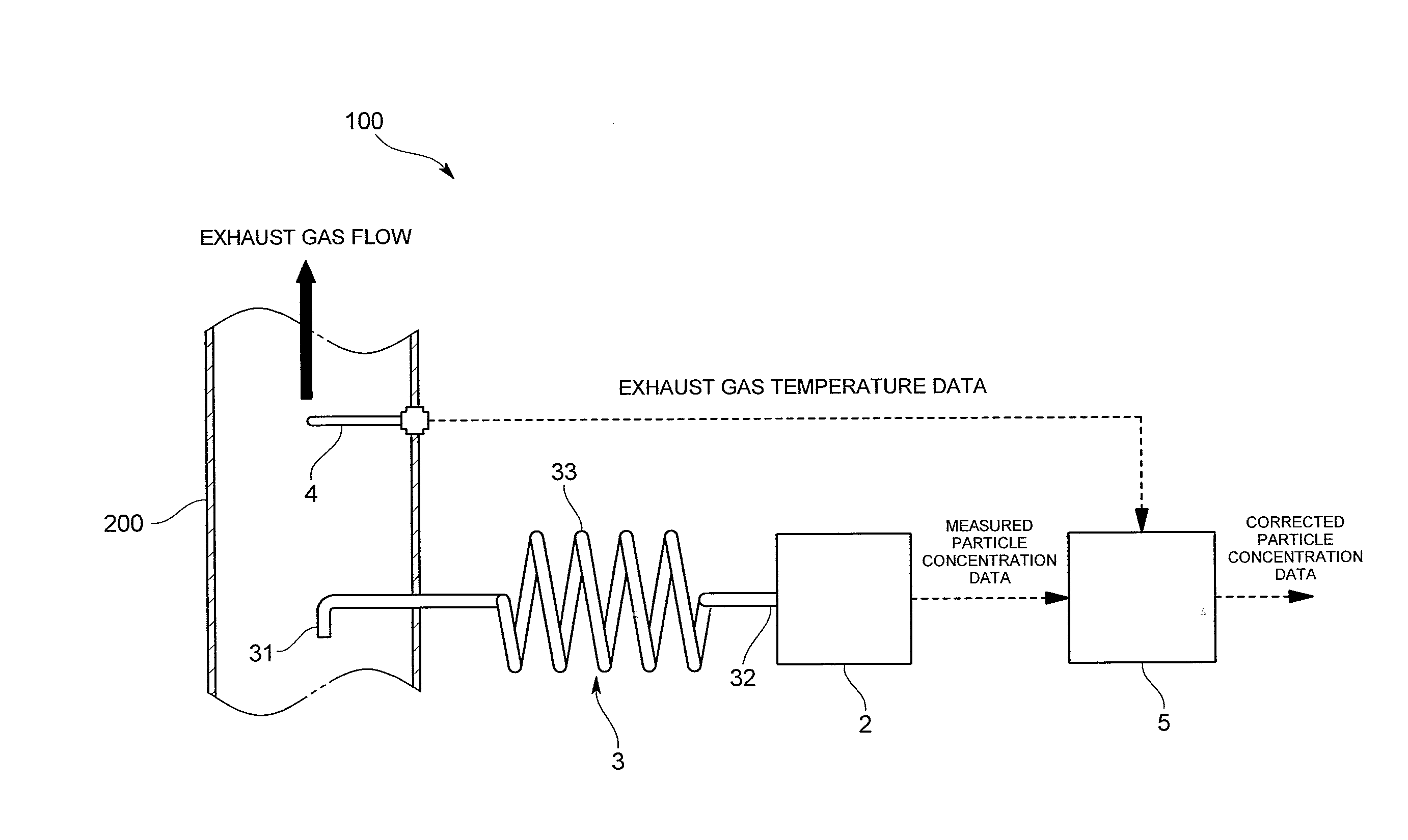
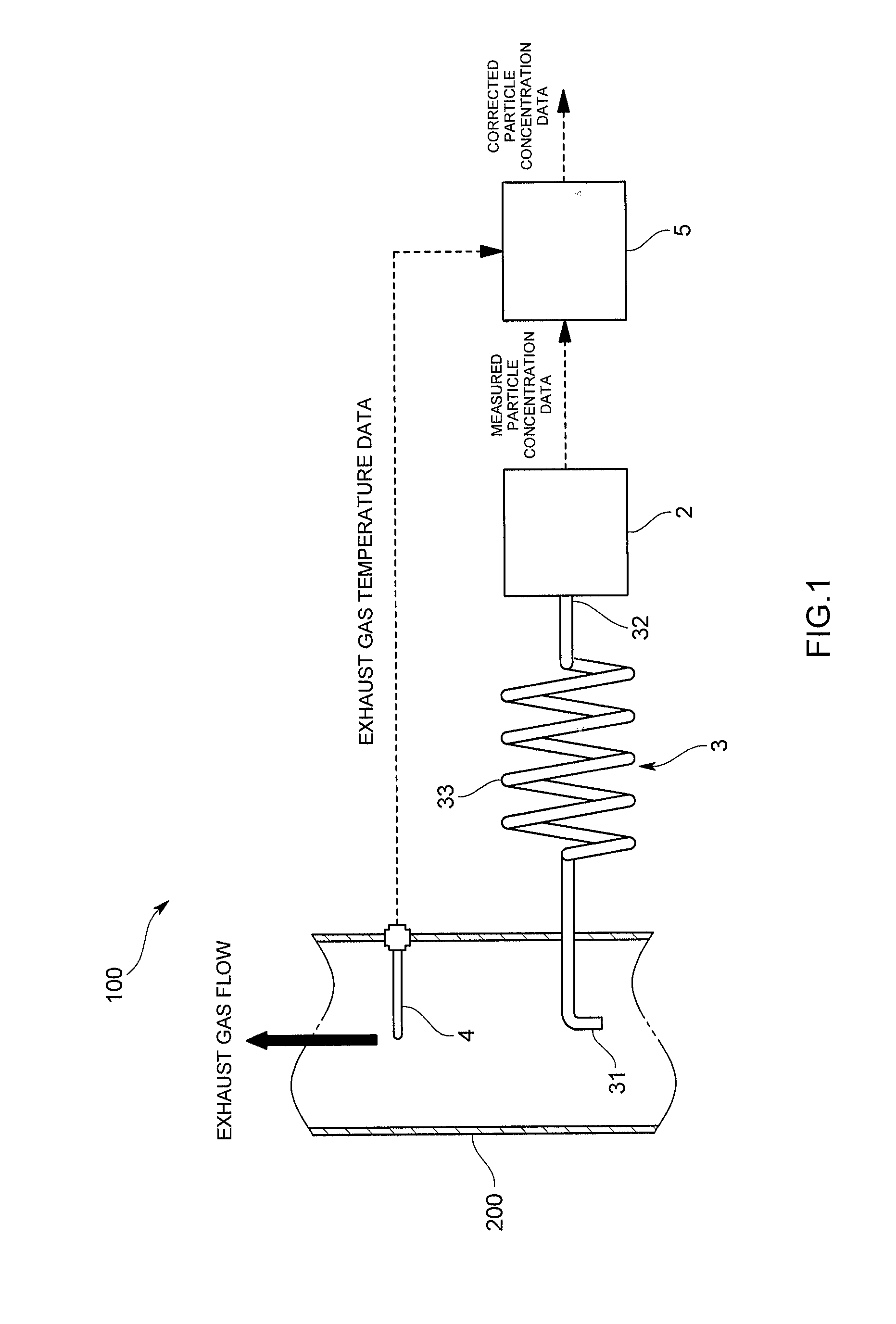
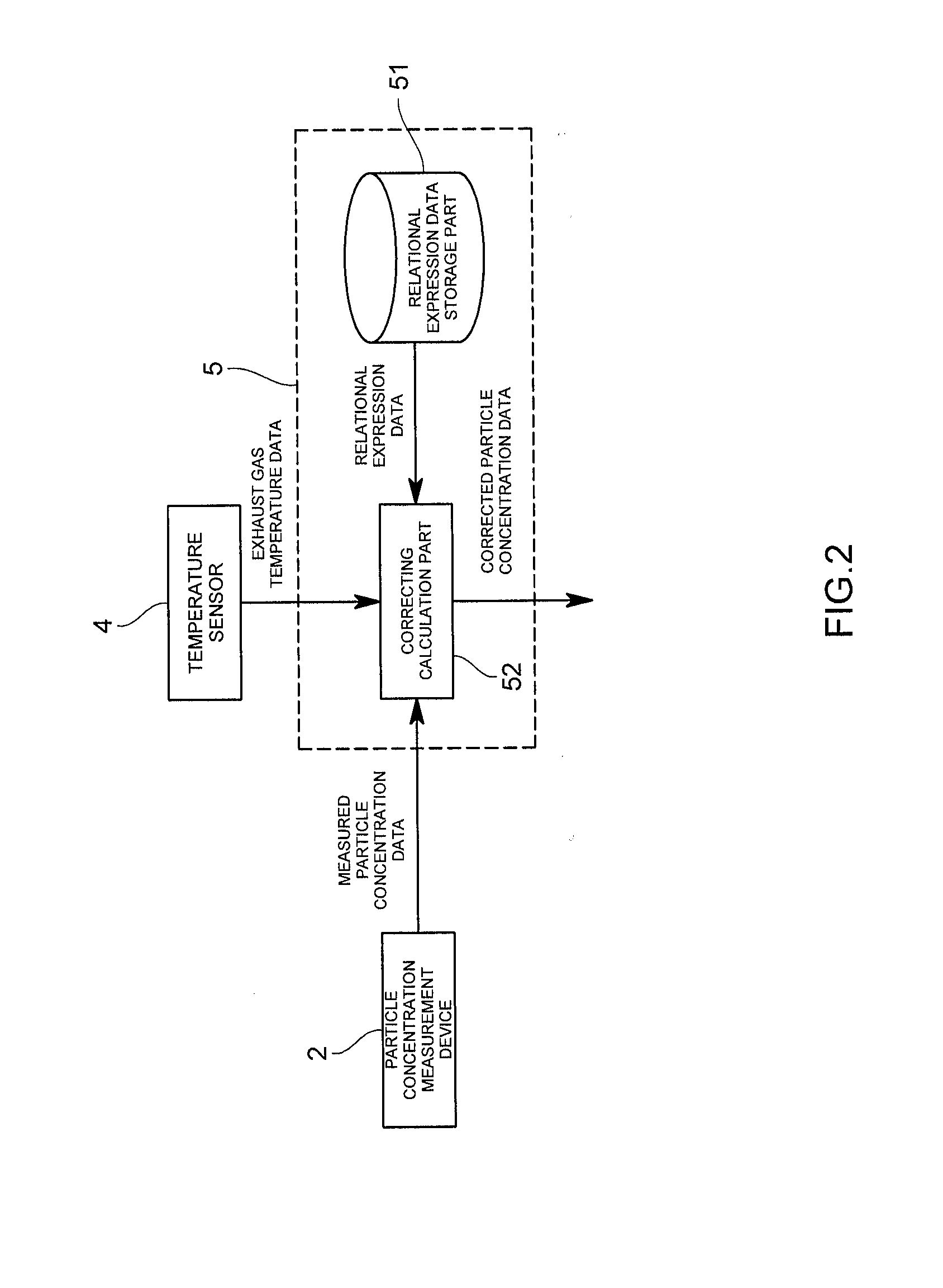
[0029]An exhaust gas analysis system 100 according to the present embodiment is, as illustrated in FIG. 1, one that measures particle concentration of particulate matter (PM, hereinafter also simply referred to as particles) having a size of, for example, 1 μm or less contained in exhaust gas that flows through an exhaust pipe 200 serving as an exhaust gas transfer pipe connected to an internal combustion engine such as a diesel engine. Note that the particulate matter includes soot that is atomic carbon (soot), soluble organic fractions (SOF) from unburnt fuel and lubricating oil, sulfuric acid and sulfate, and the like. Also, the particle concentration refers to the number of particles (or number concentration), mass concentration of the particles, volume concentration of the particles, or the like. In the following embodiment, the case...


PUM


Abstract

The present invention is one that, even while cooling exhaust gas without dilution, makes it possible to accurately measure particle concentration, and provided with: a particle concentration measurement device; a sampling cooling pipe that cools the exhaust gas collected from an exhaust gas transfer pipe to a measurable temperature of the particle concentration measurement device without dilution, and introduces the cooled exhaust gas into the particle concentration measurement device; a temperature sensor that detects temperature of the exhaust gas flowing into an exhaust gas inlet; and a calculation device that, from the detected temperature by the temperature sensor and the temperature of the exhaust gas introduced into the particle concentration measurement device, corrects measured particle concentration by the particle concentration measurement device in real time to calculate the particle concentration of the exhaust gas flowing through the exhaust gas transfer pipe.

Description

TECHNICAL FIELD[0001]The present invention relates to an exhaust gas analysis system and an exhaust gas analysis program that measure particle concentration in exhaust gas emitted from an internal combustion engine such as a diesel engine.BACKGROUND ART[0002]As a system that measures particle concentration in exhaust gas emitted from a diesel engine, for example, as disclosed in Patent literature 1, there is a system that introduces exhaust gas into a particle counting device such as a CPC to count the number of particles.[0003]Meanwhile, the exhaust gas is emitted in a high temperature state (e.g., 500° C.), and therefore in order to measure particle concentration in the exhaust gas, temperature of the exhaust gas should be reduced to a measurable temperature of the particle counting device. For this purpose, a possible method is that, by circulating the exhaust gas in the high temperature state in a pipe, the exhaust gas is cooled by thermal conduction of the pipe. However, this m...

Claims


Application Information

Patent Timeline
IPC IPC(8): G01M15/10
CPCG01N1/2252G01N2001/2282G01M15/10G01N15/06G01M15/102G01N25/22
Inventor ASANO, ICHIROSHINOHARA, MASAYOSHIHANADA, KAZUO
Owner HORIBA LTD
Why Eureka
Try Eureka