Membrane electrode assembly, fuel cell using the same and manufacturing method of membrane electrode assembly

Active Publication Date: 2013-07-11
TOYOTA JIDOSHA KK
View PDF5 Cites 24 Cited by
  • Summary
  • Abstract
  • Description
  • Claims
  • Application Information

AI Technical Summary

Benefits of technology

[0006]The object of the invention is thus to provide a technique o

Problems solved by technology

In the membrane electrode assembly, the fluffs may be stuck into the electrolyte membrane and damage the electroly

Method used


Image

  • Membrane electrode assembly, fuel cell using the same and manufacturing method of membrane electrode assembly
  • Membrane electrode assembly, fuel cell using the same and manufacturing method of membrane electrode assembly
  • Membrane electrode assembly, fuel cell using the same and manufacturing method of membrane electrode assembly

Examples


first embodiment

A. First Embodiment

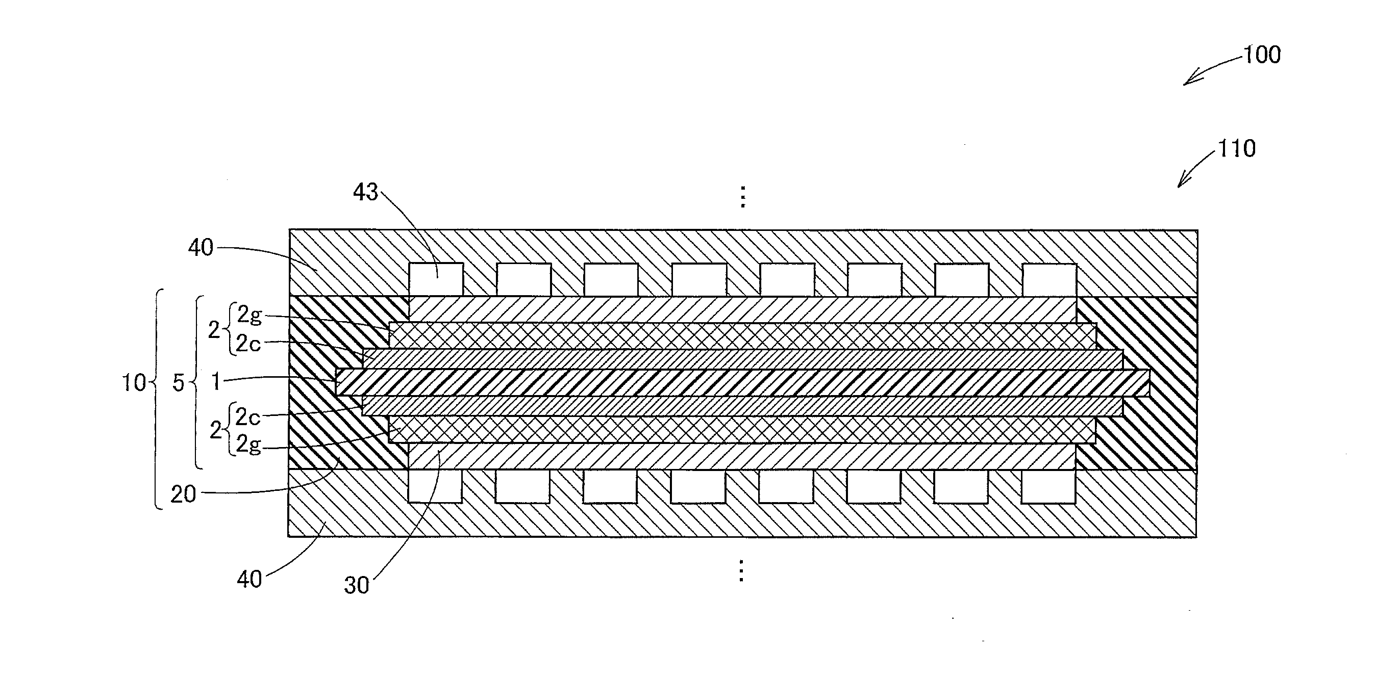
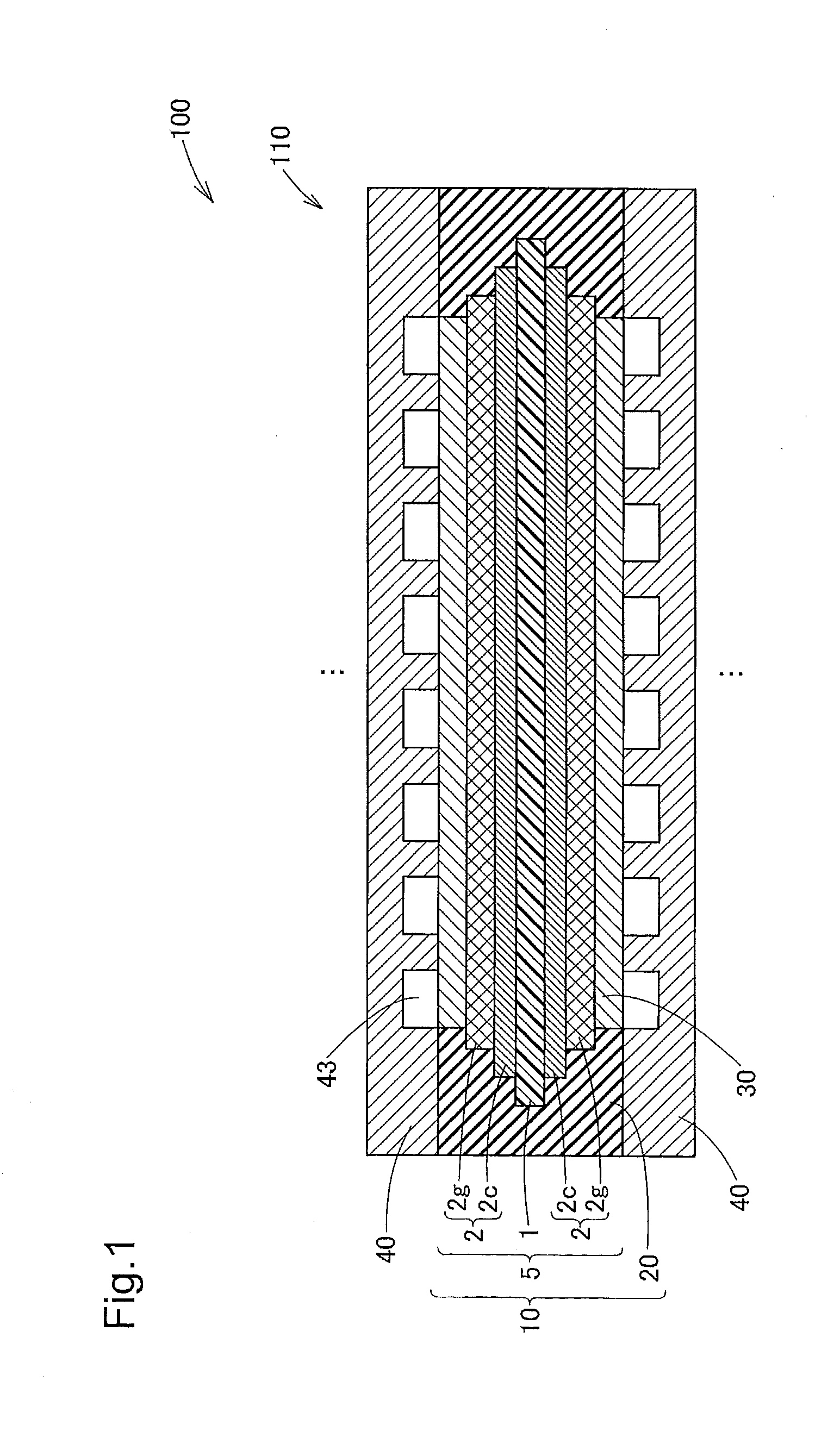
[0069]FIG. 1 is a schematic diagram illustrating the structure of a fuel cell according to one embodiment of the invention. This fuel cell 100 is provided as a polymer electrolyte fuel cell that generates electricity with received supplies of hydrogen and oxygen as reactive gases. The fuel cell 100 has the stack structure by stacking a plurality of unit cells 110 one upon another. The unit cell 100 has a seal-integrated membrane electrode assembly 10 and two separators 40 that are placed across the seal-integrated membrane electrode assembly 10.

[0070]The seal-integrated membrane electrode assembly 10 includes a membrane electrode assembly 5 and a seal member 20 placed at the outer peripheral edge of the membrane electrode assembly 5. The membrane electrode assembly 5 is provided as a power generation device where electrodes 2 having gas diffusivity are integrated with and arranged on both sides of an electrolyte membrane 1 having good proton conductivity in the we...

second embodiment

B. Second Embodiment

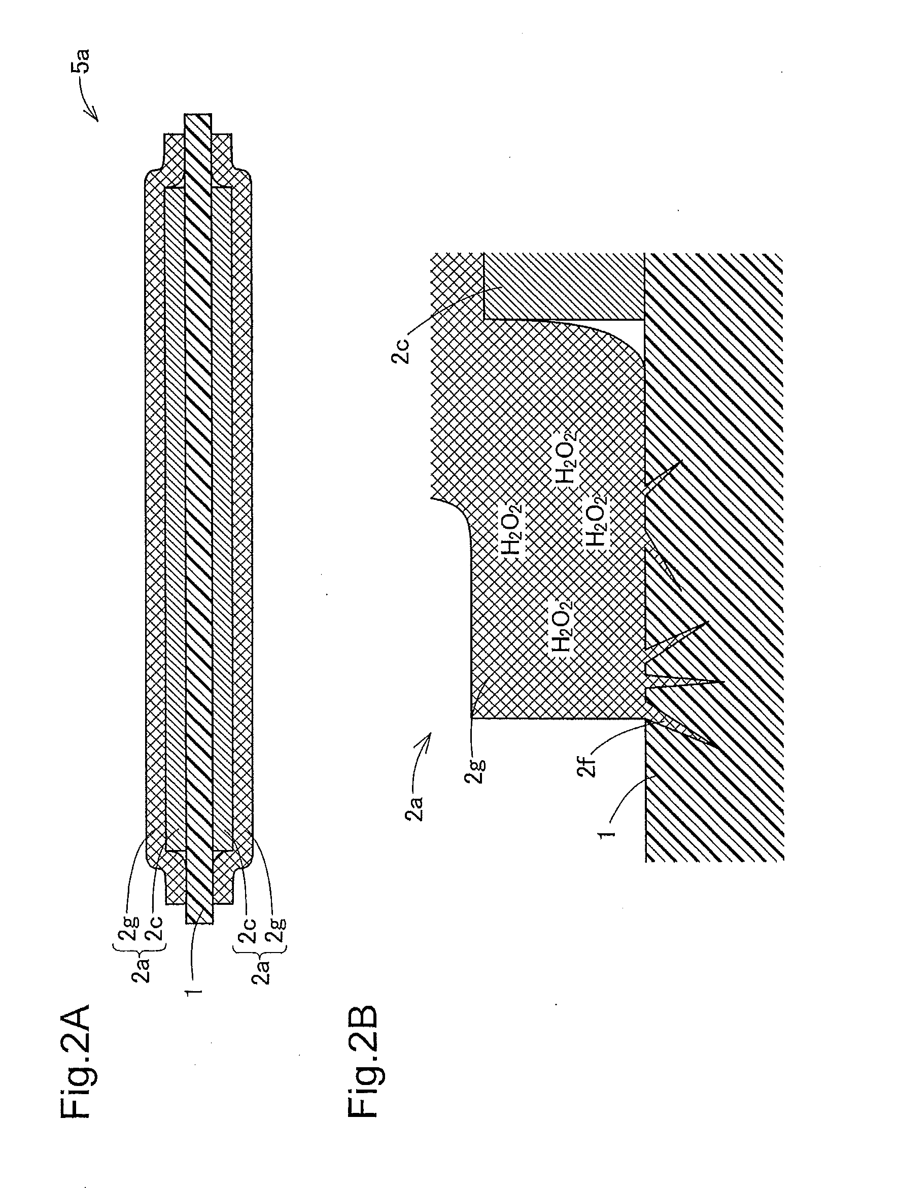
[0090]FIG. 5 is a schematic diagram illustrating the structure of a fuel cell 100A according to a second embodiment of the invention. The structure of FIG. 5 is substantially similar to the structure of FIG. 1, except the difference in structure of electrodes 2A. In a membrane electrode assembly 5A of this fuel cell 100A, the outer peripheral edge of a gas diffusion layer 2g is formed to have an inclined face that is substantially tapered toward a catalyst layer 2c-side. In other words, the end face of the gas diffusion layer 2g is arranged to form an acute angle with the surface of the gas diffusion layer 2g on the catalyst 2c-side. A water-repellent layer 3 is provided on the outer surface of the gas diffusion layer 2g. The water-repellent layer 3 covers the catalyst 2c-side surface of the gas diffusion layer 2g and part of the outer peripheral edge of the gas diffusion layer 2g.

[0091]FIGS. 6A to 6F are diagrams sequentially illustrating a process of forming t...

third embodiment

C. Third Embodiment

[0102]FIG. 9 is a schematic diagram illustrating the structure of a fuel cell 100B according to a third embodiment of the invention. The structure of FIG. 9 is substantially similar to the structure of FIG. 5, except that an electrode 2B having an outer peripheral edge of different structure from that of the electrode 2A is formed on one face of a membrane electrode assembly 5B. In the electrode 2B formed on one face of the membrane electrode assembly 5B, a catalyst layer 2c, a gas diffusion layer 2g and a water-repellent layer 3 are formed in substantially the same size as that of an electrolyte membrane 1. The electrolyte membrane 1, the catalyst layer 2c, the water-repellent layer 3 and the gas diffusion layer 2g are accordingly stacked one upon the other to have the respective end faces substantially aligned. In this fuel cell 100, oxygen and hydrogen are supplied to the electrode 2A serving as the cathode and the electrode 2B serving as the anode. The water-r...


PUM


Abstract

There is provided a technique of preventing degradation of an electrolyte membrane included in a fuel cell. A fuel cell includes a membrane electrode assembly. The membrane electrode assembly is provided as a power generation device where electrodes are arranged on both sides of an electrolyte membrane having proton conductivity. Each of the electrodes has a layered structure of stacking a catalyst layer arranged to support a catalyst and a gas diffusion layer arranged to spread a reactive gas over the entire electrode plane. The outer peripheral edge of the gas diffusion layer is located inward of the outer peripheral edge of the catalyst layer.

Description

TECHNICAL FIELD[0001]The present invention relates to a fuel cell.BACKGROUND ART[0002]The known structure of a fuel cell includes a membrane electrode assembly where electrodes are arranged on both sides of an electrolyte membrane having proton conductivity. The electrode includes a gas diffusion layer arranged to spread a reactive gas over the entire electrode plane and a catalyst layer arranged to support a catalyst for accelerating the fuel cell reaction (PTL1).[0003]During power generation of the fuel cell, hydrogen and oxygen as the reactive gases may respectively pass through the electrolyte membrane and migrate to the opposite electrodes to the electrodes that originally receive the respective supplies of the reactive gases. In such cases, hydrogen and oxygen may be present simultaneously on the same electrode side of the membrane electrode assembly and may react with each other to produce hydrogen peroxide. The produced hydrogen peroxide may be radicalized to hydrogen peroxi...

Claims


Application Information

Patent Timeline
IPC IPC(8): H01M8/10
CPCH01M8/0271H01M8/0276Y02E60/521H01M8/1004H01M2008/1095H01M8/0297Y02E60/50Y02P70/50H01M8/2404H01M8/241
Inventor TSUBOSAKA, KENJIYOSHIKAWA, HIROONAKANISHI, JUNJI
Owner TOYOTA JIDOSHA KK
Why Eureka
Try Eureka