Processing apparatus and valve operation checking method

a technology of processing apparatus and valve, which is applied in the direction of pulse technique, semiconductor/solid-state device testing/measurement, instruments, etc., can solve the problems of system difficulty in monitoring the opening and closing, the possibility of forming a poor film, and the failure of the valve and the degradation of the valve components

Active Publication Date: 2013-07-18
TOKYO ELECTRON LTD
View PDF0 Cites 13 Cited by
  • Summary
  • Abstract
  • Description
  • Claims
  • Application Information

AI Technical Summary

Benefits of technology

[0018]In view of the above, the present invention provides a processing apparatus and a valve operation checking method capable of detecting on a real time basis or preventing in advance occurrence of an abnormality of a valve by checking an operation status of the valve in a gas supply system for supplying a gas into a processing chamber.
[0019]In accordance with a first aspect of the present invention, there is provided a processing apparatus including: a processing chamber configured to accommodate a target object to be processed; gas supply paths provided in a corresponding relationship with the kinds of process gases supplied into the processing chamber; valves respectively arranged in the gas supply paths to open and close the gas supply paths; valve drive units configured to independently drive the valves; sensor units configured to independently monitor opening and closing operations of the valves; and a control unit configured to determine operation statuses of the valves based on valve opening and closing drive signals transmitted to the valve d

Problems solved by technology

For that reason, troubles such as failure of the valve and degradation of the valve components can be more frequently made in the ALD method than in the CVD method.
If the opening and closing of the valve is not accurately performed as instructed by the control unit, the possibility of forming a poor film will be increased.
Since the opening and closing speed of the valve is very fast in the ALD apparatus, there is a problem in that a conventional control system has a difficulty in monitoring the opening and closing of the valve on a real time basis to check the operation status of the valve.
Thus, it may be time-consuming to detect the trouble of the valve becau

Method used


Image

  • Processing apparatus and valve operation checking method
  • Processing apparatus and valve operation checking method
  • Processing apparatus and valve operation checking method

Examples


first embodiment

1. First Embodiment

Configuration Example of Film Forming Apparatus

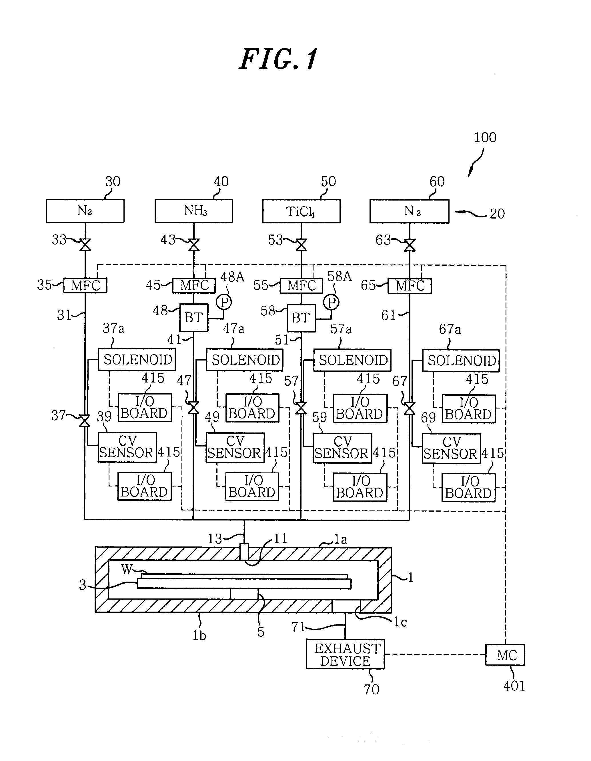
[0045]First, a processing apparatus in accordance with a first embodiment of the present invention will be described with reference to FIG. 1. FIG. 1 shows a schematic configuration of a film forming apparatus 100 of the first embodiment configured to perform a film forming process on a substrate, e.g., a semiconductor wafer W by using an ALD method. The film forming apparatus 100 includes a hermetically sealed processing chamber 1 of a substantially cylindrical shape. In the processing chamber 1, there is provided a susceptor 3 for horizontally supporting the wafer W as a target object to be processed. The susceptor 3 is supported by a cylindrical support member 5. A heater (not shown) is embedded in the susceptor 3. The wafer W is heated to a predetermined temperature by feeding electric power to the heater.

[0046]A gas introduction unit 11 is provided at a ceiling wall 1a of the processing chamber 1. A gas injection...

second embodiment

2. Second Embodiment

[0120]Next, a film forming apparatus in accordance with a second embodiment of the present invention will be described with reference to FIGS. 6 to 10.

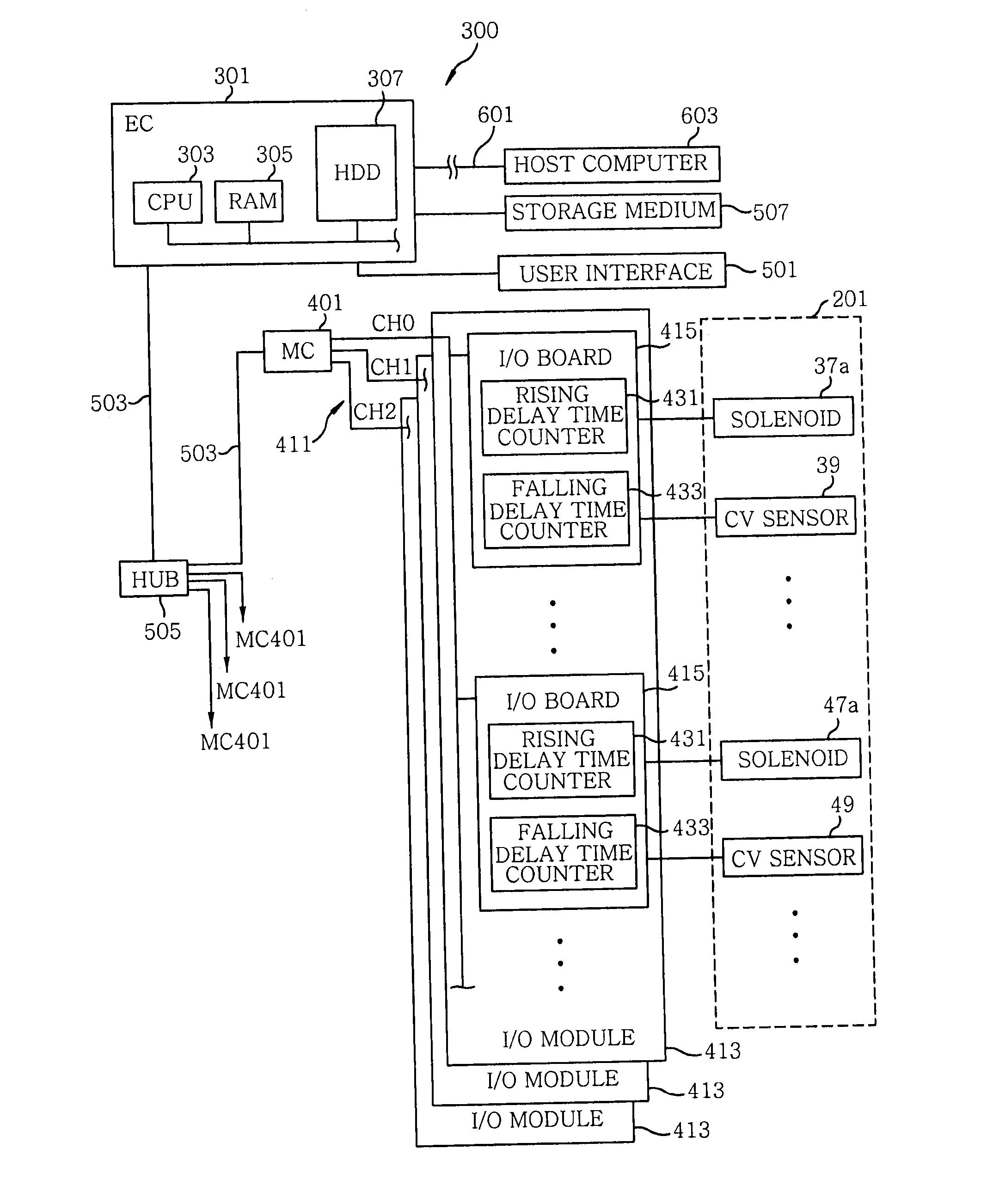
[0121]In the present embodiment, as shown in FIG. 6, two kinds of counter units for measuring a relative time difference between a feedback DI signal of a drive DO signal including one or more valve opening / closing drive signals for each of the solenoids 37a, 47a, 57a and 67a and a DI signal including one or more valve opening / closing detection signals from each of the CV sensors 39, 49, 59 and 69 are provided in each of the I / O boards 415, which is a lower-hierarchy control device compared to the module controller 401.

[0122]The first kind of counter unit is a rising delay time counter 431 for measuring a rising delay time of each of the chamber valves 37, 47, 57 and 67 obtained based on the rising time difference between the two DI signals. The second kind of counter unit is a falling delay time counter 433 for me...

third embodiment

3. Third Embodiment

[0151]Next, a film forming apparatus in accordance with a third embodiment of the present invention will be described with reference to FIGS. 11 to 13. The film forming apparatus of the present embodiment includes a counter unit for detecting and counting the simultaneous opening state of two or more chamber valves.

[0152]More specifically, as shown in FIG. 11, the I / O board 415, which is a lower-hierarchy control device compared to the module controller 401, is configured to include a simultaneous opening counter 441 for detecting and counting the simultaneous opening state of two or more of the chamber valves 37, 47, 57 and 67 by using each of the CV sensor DI signals transmitted from the CV sensors 39, 49, 59 and 69.

[0153]In the film forming apparatus of the present embodiment, the components other than the counter unit are the same as those of the film forming apparatus 100 of the first embodiment. The following description will be focused on the different poin...


PUM

PropertyMeasurementUnit
Timeaaaaaaaaaa

Abstract

A processing apparatus includes a processing chamber configured to accommodate a target object to be processed, gas supply paths provided in a corresponding relationship with the kinds of process gases supplied into the processing chamber, and valves respectively arranged in the gas supply paths to open and close the gas supply paths. The processing apparatus further includes valve drive units configured to independently drive the valves, sensor units configured to independently monitor opening and closing operations of the valves, and a control unit configured to determine operation statuses of the valves based on valve opening and closing drive signals transmitted to the valve drive units and/or valve opening and closing detection signals transmitted from the sensor units.

Description

CROSS-REFERENCE TO RELATED APPLICATIONS[0001]This application claims priority to Japanese Patent Application No. 2012-006161 filed on Jan. 16, 2012 and Japanese Patent Application No. 2012-261339 filed on Nov. 29, 2012, the entire contents of which are incorporated herein by reference.FIELD OF THE INVENTION[0002]The present invention relates to a processing apparatus for performing a film forming process or the like by supplying a processing gas on a target object to be processed, e.g., a semiconductor wafer, and a valve operation checking method for checking an operation status of a valve in the processing apparatus to detect or prevent an abnormality.BACKGROUND OF THE INVENTION[0003]In a manufacturing process of a semiconductor device, a target object to be processed such as a semiconductor wafer or the like is repeatedly subjected to various kinds of processing such as a film forming, an etching, a heat treatment and a modification treatment. For example, there is known a CVD (Ch...

Claims


Application Information

Patent Timeline
IPC IPC(8): C23C16/52H03K21/00G01M13/00
CPCH03K21/023C23C16/52G01M13/00H03K21/00F16K37/0041C23C16/45561F16K37/00C23C16/4551C23C16/45544G01M13/003H01L21/205H01L22/00
Inventor HIROSE, KATSUHITOMIYAZAWA, TOSHIOHIRATA, TOSHIHARUTANAKA, TOSHIMASA
Owner TOKYO ELECTRON LTD
Why Eureka
Try Eureka