Ignition delay period estimation apparatus and ignition time control apparatus for internal combustion engine

a technology of ignition delay and estimation apparatus, which is applied in the direction of electrical control, instruments, nuclear elements, etc., can solve the problems of significant ignition delay of air-fuel mixture in diesel engines, and generation of combustion air-fuel mixture, so as to improve the reliability of ignition delay period estimation and improve the effect of exhaust emission

Inactive Publication Date: 2013-08-01
TOYOTA JIDOSHA KK
View PDF4 Cites 9 Cited by
  • Summary
  • Abstract
  • Description
  • Claims
  • Application Information

AI Technical Summary

Benefits of technology

[0034]According to the present invention, conditions that affect whether or not the air-fuel mixture in a combustion field is ignited are directly recognized to estimate an ignition delay period by estimating the air-fuel ignition delay period based on an equivalence ratio in a fuel spray, thereby improving the reliability of the ignition delay period estimation. Further, an appropriate ignition time can be achieved by controlling the ignition time based on the reliable result of estimation of the ignition delay period, and it is possible to achieve improvement of exhaust emission and the like.

Problems solved by technology

Specifically, when a fuel injection from an injector into a combustion chamber is started, first, a combustible air-fuel mixture is generated due to evaporative diffusion of fuel (an ignition delay period).
Specifically, it is possible that ignition delay of air-fuel mixture will be significant under such conditions as when running in a highland where the altitude is high, in the case where fuel properties (e.g., cetane number) is worse than standard properties (in the case where a low-cetane number fuel is used), when the outside air temperature is low, or when an engine load rapidly changes (at the time of operation transients).
Ignition delay of air-fuel mixture in a diesel engine includes physical ignition delay and chemical ignition delay.
The physical ignition delay is a period of time required for evaporation / mixture of fuel droplets.
On the other hand, the chemical ignition delay is a period of time required for chemical bonding / decomposition and exothermic oxidation of fuel vapor.

Method used


Image

  • Ignition delay period estimation apparatus and ignition time control apparatus for internal combustion engine
  • Ignition delay period estimation apparatus and ignition time control apparatus for internal combustion engine
  • Ignition delay period estimation apparatus and ignition time control apparatus for internal combustion engine

Examples


Embodiment Construction

[0050]Embodiments of the invention are described below with reference to the drawings. In these embodiments, a case will be described in which the present invention is applied to a common rail in-cylinder direct injection multi-cylinder (for example, inline four-cylinder) diesel engine (compression self-ignition internal combustion engine) mounted in an automobile.

[0051]—Engine Configuration—

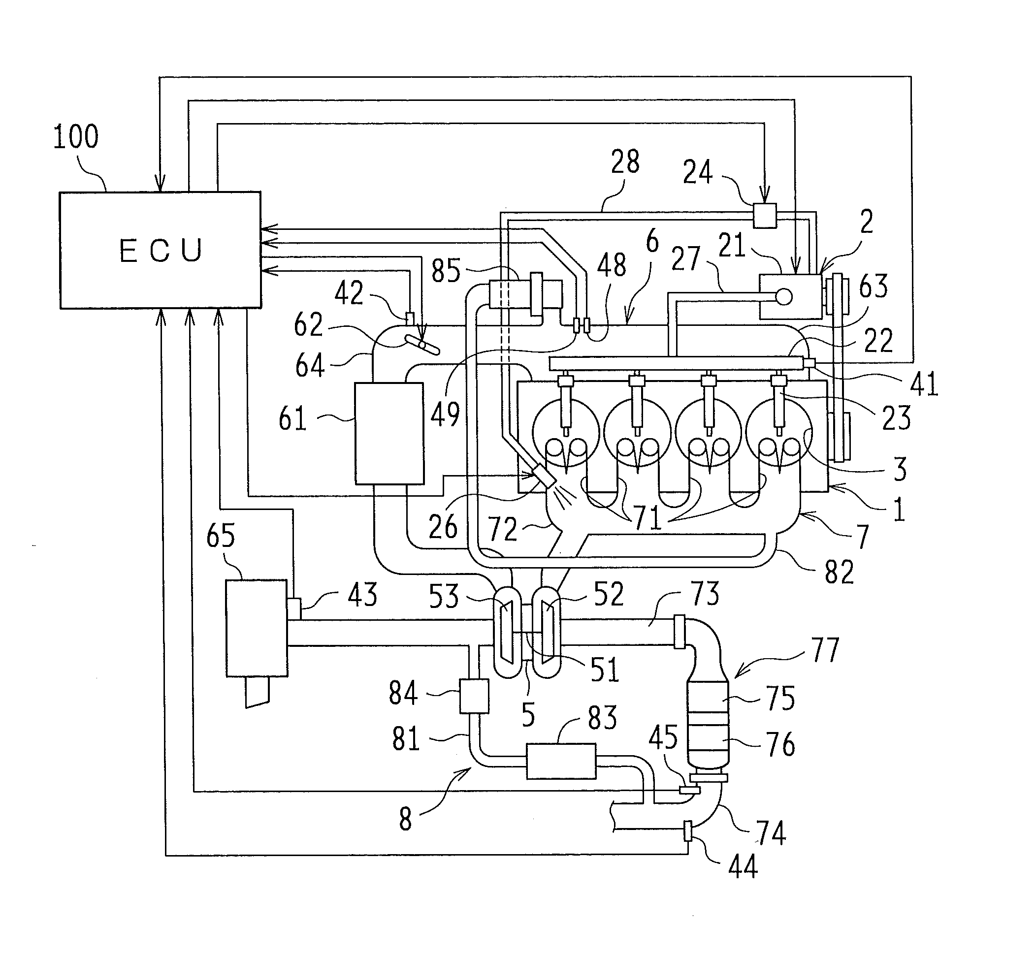
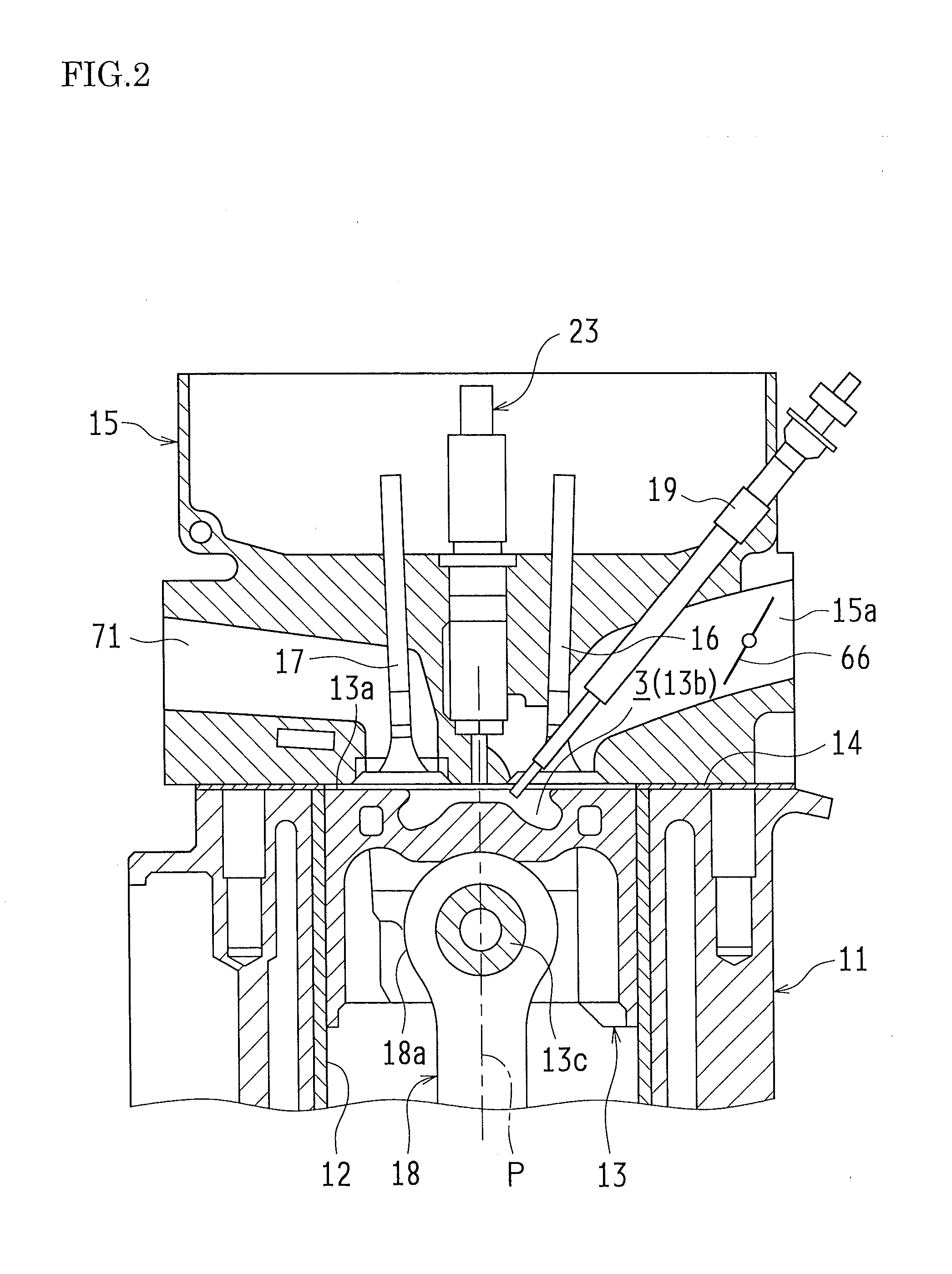
[0052]First, the overall configuration of a diesel engine (hereinafter simply referred to as the engine) according to the present embodiment will be described. FIG. 1 is a schematic configuration diagram of an engine 1 and a control system of the engine 1 according to the present embodiment. Also, FIG. 2 is a cross-sectional diagram showing combustion chambers 3 of the diesel engine and their surroundings.

[0053]As shown in FIG. 1, the engine 1 according to the present embodiment is configured as a diesel engine system having a fuel supply system 2, the combustion chambers 3, an intake system 6, ...


PUM


Abstract

A period of time from a point in time at which pilot injection is executed until an equivalence ratio in fuel spray, after exceeding a combustible equivalence ratio, falls below the combustible equivalence ratio is calculated as a physical ignition delay period. A chemical ignition delay period is calculated from the temperature and pressure inside a combustion chamber at a point in time at which the equivalence ratio in the fuel spray reached the combustible equivalence ratio. A total ignition delay period is calculated from the above-calculated ignition delay periods. The oxygen concentration and temperature inside the combustion chamber are adjusted such that the total ignition delay period matches a target ignition delay period.

Description

TECHNICAL FIELD[0001]The present invention relates to apparatuses for estimating an ignition delay period of compression self-ignition internal combustion engines represented by diesel engines, and to apparatuses for controlling an ignition time by achieving an appropriate ignition delay period. In particular, the present invention relates to measures to improve the accuracy of estimation of the ignition delay period.BACKGROUND ART[0002]Combustion of a diesel engine mounted in an automobile or the like is known to be mainly executed in the form of premixed combustion and diffusion combustion. Specifically, when a fuel injection from an injector into a combustion chamber is started, first, a combustible air-fuel mixture is generated due to evaporative diffusion of fuel (an ignition delay period). Next, this combustible air-fuel mixture undergoes self-ignition nearly simultaneously at several locations in the combustion chamber, and combustion progresses rapidly (premixed combustion)....

Claims


Application Information

Patent Timeline
Patent Type & Authority Applications(United States)
IPC IPC(8): F02D41/04
CPCF02D35/023F02D35/025F02D35/028F02D41/04F02D41/403Y02T10/44F02D41/047Y02T10/40
Inventor HASEGAWA, RYO
Owner TOYOTA JIDOSHA KK
Why Eureka
Try Eureka