Single Well, Self-Flowing, Geothermal System for Energy Extraction

a geothermal system and well technology, applied in the direction of machines/engines, borehole/well accessories, insulation, etc., can solve the problems of depletion of dry steam power plant installations, dry steam power plants, etc., and achieve the effect of reducing the amount of water in the original sub-surface water tabl

Active Publication Date: 2013-08-01
DEEP WELL POWER
View PDF6 Cites 24 Cited by
  • Summary
  • Abstract
  • Description
  • Claims
  • Application Information

AI Technical Summary

Benefits of technology

[0030]Further, the well casing used in the geothermal power systems disclosed herein may be tightly sealed to provide a closed loop for the working fluid, thereby enabling various portions of the well casing, between the casing interior surface and a working fluid line exterior surface, to be used to circulate working fluid.

Problems solved by technology

(1) Dry steam power plants, which capture and use steam exiting from natural fissures in sub-surface rock, where deeper water has been boiled into steam via sub-surface heat, to drive a power generation turbine, with the turbine typically producing electricity. Dry steam power plants, however, are typically limited for use in areas that have naturally occurring conditions that are suitable for such use, and therefore there are relatively few dry steam power plant installations.
(2) Flash steam geothermal power plants, in which high-temperature and high-pressure water (typically at water temperatures around, or greater than, 180° C.) is artificially pumped (via large mechanical water pumps) under high pressure from typically deep wells to the surface. Upon reaching the surface, all or a portion of the very hot and high-pressure water is flashed into steam that may be used to drive turbines and / or generators.
However, in such flash steam plant systems, depletion of the original sub-surface water table is a serious environmental concern, as a significant amount of the sub-surface water may not condense and return to the basin, thereby necessitating the use of large-scale re-injection pumps to force the remaining condensation back down a separate return well.
Flash steam plants also use transport lines that are susceptible to mineral scaling by the brine water, which is an extremely significant problem that may necessitate frequent and costly de-scaling operations.
Still further, there are only a limited number of geographic locations that have conditions suitable to sufficiently pressurize water to produce viable amounts of electrical power, and it is economically infeasible to install and operate a flash steam plant in some of these locations.
To be economically feasible for power production, the temperature of the hot water exiting the well may need to be 180° C. or more, and it is often costly to access sub-surface locations where the necessary heat and pressure naturally occur.
Further, the use of large water pumps to pump water into and / or out of the well results in a significant parasitic load of the well's power production capacity.
However, such “hot spots” are relatively rare and are sought after for use by flash steam plant systems.
Therefore, at least one (and typically two) large, power-consuming, water circulating pump(s) is / are necessary, among other equipment, for a flash steam power production plant.
Also, as mentioned, the scaling of minerals on the interior walls of the brine water transport lines poses a serious maintenance cost issue, since, unless the continuous build up of scaling is removed, the design brine water flow is restricted and design flow rates and corresponding power production levels are impaired.
However, in either a binary or an EGS geothermal power system, the power consumption required by the one or more primary working fluid water / brine circulating pumps is a significant parasitic electrical load that reduces the effective amount of electrical power generated by the system.
Thus, the current binary geothermal power production plants require somewhat uniquely occurring circumstances to be economically viable, typically require at least two independent fluid loops (with typically at least two to three artificial and power parasitic liquid pumps required for system operation), and the geothermal “hot spots” generally necessary for economic viability are not universally available.
Binary systems utilizing waste heat sources are more common, but either nuclear or fossil fuels are typically required as the primary heat source, both of which present well-understood environmental drawbacks.
The EGS designs may present additional environmental drawbacks by: producing seismic activity when fracturing hot dry rocks between deep wells; contributing to groundwater pollution when rock fracturing chemicals seep into aquifers; releasing significant quantities of carbon dioxide emissions (sometimes almost as much as that produced by a coal-fired power plant); and losing significant quantities of water on a continuous basis via condensing efforts at the surface and / or in the lowermost open loop portion of the deep wells deep (thereby depleting otherwise available natural water supplies).
While there are other known renewable and generally environmentally safe alternative energy sources, such as solar and wind, these alternative power sources are contingent upon uncontrollable conditions, such as the availability of sufficient sunshine or wind.
Consequently, these more environmentally friendly alternatives are not reliable for day-to-day, consistent energy production.

Method used


Image

  • Single Well, Self-Flowing, Geothermal System for Energy Extraction
  • Single Well, Self-Flowing, Geothermal System for Energy Extraction
  • Single Well, Self-Flowing, Geothermal System for Energy Extraction

Examples


Embodiment Construction

[0039]The following detailed description is not intended in a limiting sense, and is made solely for the purpose of illustrating the general principles of this subject matter. The various features and advantages of the present disclosure may be more readily understood with reference to the following detailed description taken in conjunction with the accompanying drawings.

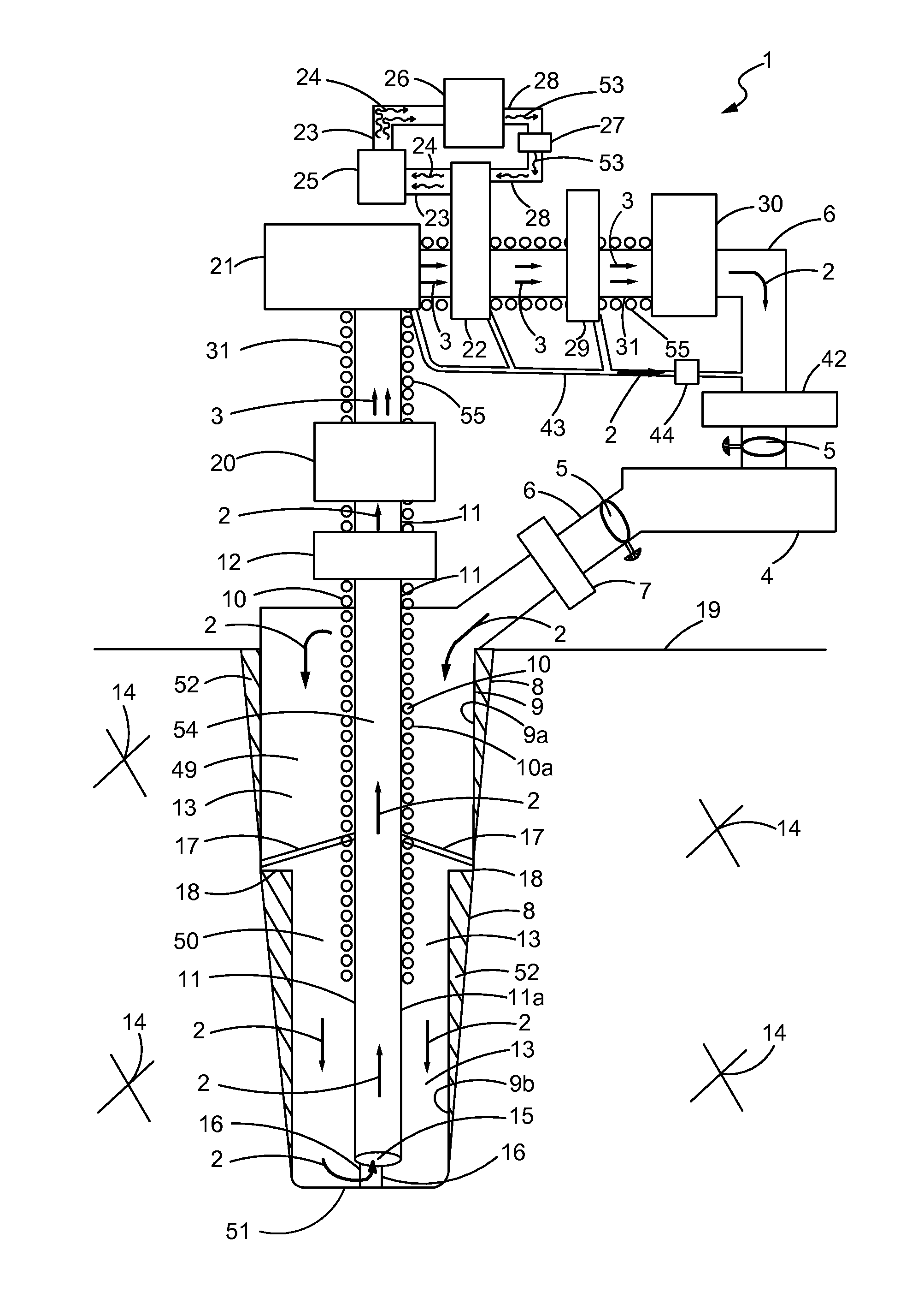
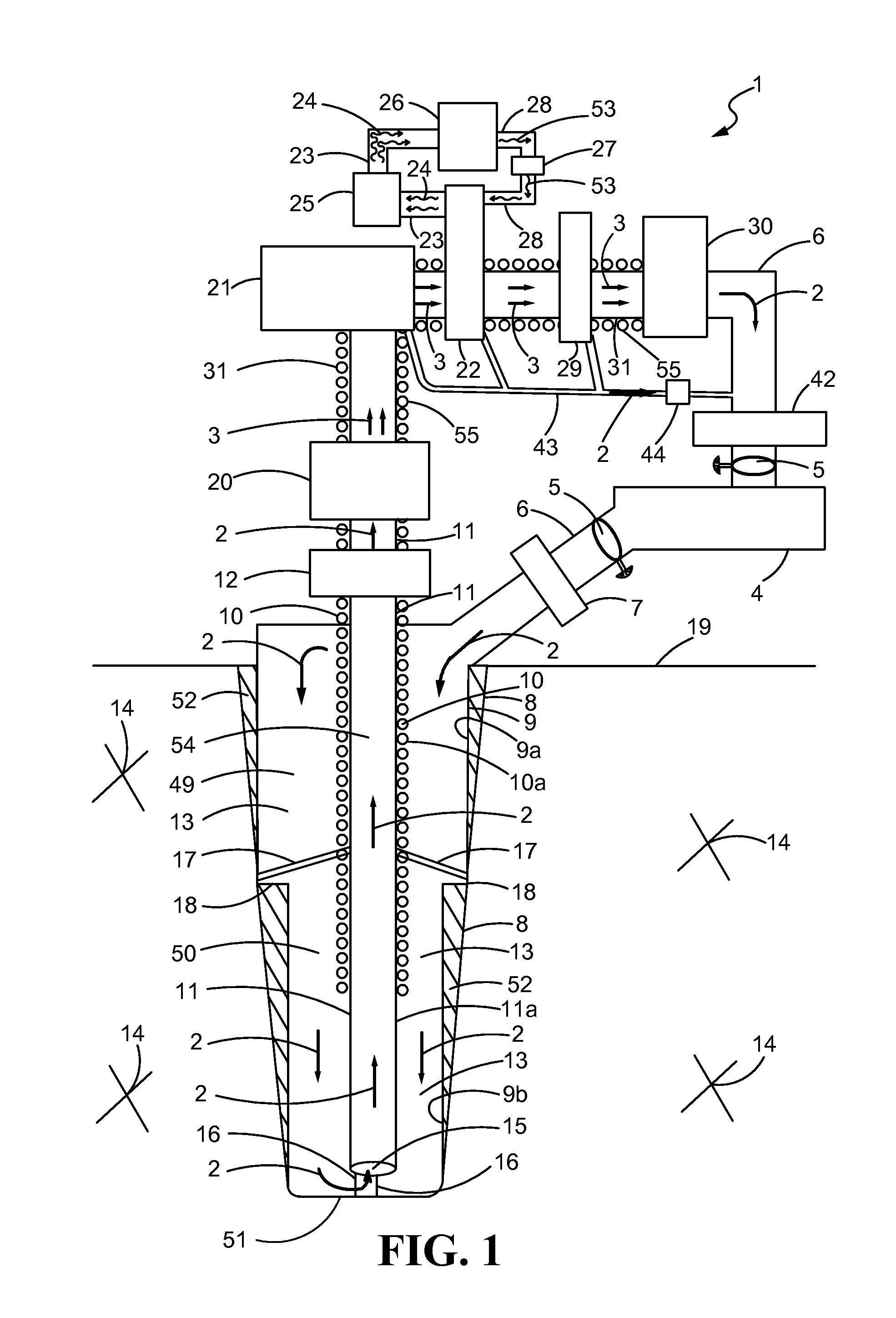
[0040]Referring now to the drawings in detail, where like numerals refer to like parts or elements, FIG. 1 is a side view, not drawn to scale, of a single well, self-flowing, geothermal system 1 for at least one of power generation, heat acquisition, and energy extraction. The system 1 may have a liquid phase working fluid (the working fluid is not shown, but its directional flow is indicated by a single arrow 2 in its liquid phase, and is indicated by double arrows 3 in its vapor phase) stored in a liquid holding tank 4. For the working fluid flow direction 2 through a well 8 as shown in FIG. 1, advantageous workin...


PUM


Abstract

A renewable energy, single well, primarily self-flow, geothermal heat/power production system that acquires naturally occurring sub-surface geothermal heat to heat water and/or produce mechanical/electrical power using a heat exchangers or a turbine/generator. The sub-surface structures defining a working fluid flow path may be insulated, such as with vacuum insulation, to increase system efficiency and ensure a substantially self-generating working fluid flow.

Description

CROSS-REFERENCE TO RELATED APPLICATIONS[0001]This application claims the benefit of: U.S. Provisional Patent Application No. 61 / 612,615, filed on Mar. 19, 2012; U.S. Provisional Patent Application No. 61 / 668, 238, filed on Jul. 5, 2012; U.S. Provisional Patent Application No. 61 / 703,986, filed on Sep. 21, 2012; U.S. Provisional Patent Application No. 61 / 714,784, filed on Oct. 17, 2012; U.S. Provisional Patent Application No. 61 / 591,551, filed on Jan. 27, 2012; and U.S. Provisional Patent Application No. 61 / 657,223, filed on Jun. 8, 2012.FIELD OF THE DISCLOSURE[0002]The present disclosure generally relates to geothermal energy extraction systems.BACKGROUND OF THE DISCLOSURE[0003]Geothermal energy extraction systems, such as geothermal power generating systems, are known as renewable energy sources with relatively low carbon emission footprints. A traditional geothermal power system generally may be classified in one of three conventional types, as follows:[0004](1) Dry steam power pl...

Claims


Application Information

Patent Timeline
Patent Type & Authority Applications(United States)
IPC IPC(8): E21B43/24
CPCE21B43/24E21B36/001F24J2003/087F03G7/04F24J3/086Y02E10/16F24T10/30F24T2010/50Y02E10/10
Inventor WIGGS, B. RYLAND
Owner DEEP WELL POWER
Why Eureka
Try Eureka