Voltage reference generation circuit using gate-to-source voltage difference and related method thereof, and voltage regulation circuit having common-source configuration and related method thereof

a voltage reference and gate-to-source voltage difference technology, applied in the direction of electric variable regulation, process and machine control, instruments, etc., can solve the problems of low temperature coefficient, weak body effect etc., and achieve low temperature coefficient, low fabrication cost, and wideband high psrr

Active Publication Date: 2013-08-01
SPI ELECTRONICS
View PDF27 Cites 3 Cited by
  • Summary
  • Abstract
  • Description
  • Claims
  • Application Information

AI Technical Summary

Benefits of technology

[0016]The proposed voltage reference generation circuit has a low temperature coefficient, a wideband high PSRR, low fabrication cost, a weak body effect and / or low line regulation, and therefore provides a solution to power supply noise suppression in wideband application.

Problems solved by technology

As it is expensive to fabricate a BJT with a bipolar complementary metal-oxide-semiconductor (BiCMOS) process, the parasitic effect of the standard complementary metal-oxide-semiconductor (CMOS) process is commonly used for BJT fabrication.
However, because a base of the fabricated parasitic BJT has to be connected to ground and occupies a large area, the voltage reference circuit fabricated with the above process may have limited application.
In addition, when the voltage reference generation circuit 200 operates at a higher operation frequency, the PSRR would be greatly reduced, resulting in limited wideband application of the voltage reference generation circuit 200.
Unfortunately, the voltage reference generation circuit 300 exhibits higher sensitivity to temperature variations.
Thus, how to implement a voltage reference generation circuit having a low temperature coefficient, a high PSRR, low fabrication cost and a weak body effect is a problem that needs to be solved.

Method used


Image

  • Voltage reference generation circuit using gate-to-source voltage difference and related method thereof, and voltage regulation circuit having common-source configuration and related method thereof
  • Voltage reference generation circuit using gate-to-source voltage difference and related method thereof, and voltage regulation circuit having common-source configuration and related method thereof
  • Voltage reference generation circuit using gate-to-source voltage difference and related method thereof, and voltage regulation circuit having common-source configuration and related method thereof

Examples


Embodiment Construction

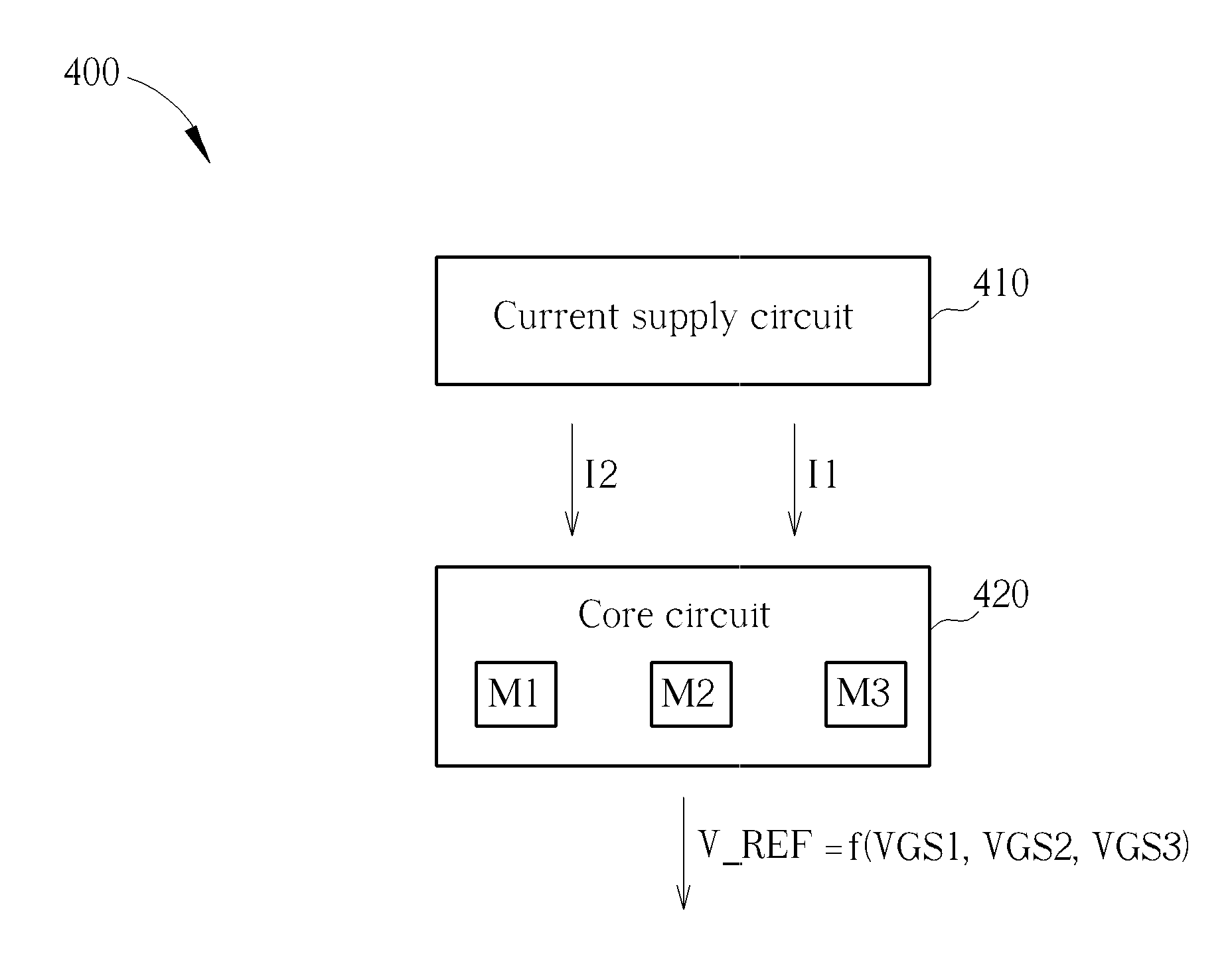
[0030]First, in accordance with an embodiment of the present invention, a circuit architecture which may enhance a PSRR without voltage regulation is disclosed. Please refer to FIG. 4, which is a block diagram illustrating an exemplary generalized voltage reference generation circuit according to an embodiment of the present invention. The voltage reference generation circuit 400 may include a current supply circuit 410 and a core circuit 420. The core circuit 420 may include, but is not limited to, a first transistor M1, a second transistor M2 and a third transistor M3. The current supply circuit 410 is arranged to provide a plurality of currents including a first current I1 and a second current I2. The core circuit 420, coupled to the current supply circuit 410, is arranged to receive the currents including the first current I1 and the second current I2, and generate a voltage reference V_REF according to the received currents. More specifically, the first transistor M1 and the th...


PUM


Abstract

A voltage reference generation circuit includes a current supply circuit and a core circuit. The current supply circuit is arranged to provide a plurality of currents. The core circuit is coupled to the current supply circuit, and arranged to receive the currents and accordingly generate a voltage reference. The core circuit includes a first transistor, a second transistor and a third transistor, wherein the first transistor and the third transistor generate a first gate-to-source voltage and a third gate-to-source voltage, respectively, according to a first current of the received currents; the second transistor generates a second gate-to-source voltage according to a second current of the received currents; and the voltage reference is generated according to the first gate-to-source voltage, the second gate-to-source voltage and the third gate-to-source voltage.

Description

BACKGROUND OF THE INVENTION[0001]1. Field of the Invention[0002]The disclosed embodiments of the present invention relate to voltage reference generation mechanism, and more particularly, to a voltage reference generation circuit with a low temperature coefficient, low line regulation and / or a wideband high power supply rejection ratio, and related voltage reference generation method, voltage regulation circuit and voltage regulation method.[0003]2. Description of the Prior Art[0004]In order to design a voltage reference generation circuit with a lower temperature coefficient, a bipolar junction transistor (BJT), a diode, and a depletion-mode metal-oxide-semiconductor field effect transistor (MOSFET) are usually used for temperature compensation. For example, a BJT is used in a conventional bandgap voltage reference circuit for temperature compensation. As it is expensive to fabricate a BJT with a bipolar complementary metal-oxide-semiconductor (BiCMOS) process, the parasitic effect...

Claims


Application Information

Patent Timeline
Patent Type & Authority Applications(United States)
IPC IPC(8): G05F5/00G05F1/10
CPCG05F5/00G05F1/10G05F3/242
Inventor PAN, SHENG-WEN
Owner SPI ELECTRONICS
Why Eureka
Try Eureka