Systems and methods for intravascular ultrasound imaging

Inactive Publication Date: 2013-08-01
GENERAL ELECTRIC CO
View PDF4 Cites 3 Cited by
  • Summary
  • Abstract
  • Description
  • Claims
  • Application Information

AI Technical Summary

Benefits of technology

[0011]Certain aspects of the present technique present an intravascular ultrasound catheter including at least one miniaturized transducer element adapted for use in an intravascular region of interest of a subject. Particularly, the miniaturized transducer element is configured to produce signals for use in generating one or more ultrasound images of the intravascular region of interest of the subject. The catheter further includes one or more apodizing structures operably connected to the transducer element. The apodizing structures are configured to decrease the responsiveness of the transducer element at one or more boundaries of the transducer element with respect to the center of the transducer element for reducing sidelobe amplitude of an ultrasound beam profile in the region of interest, thereby generating improved ultrasound images.
[0012]Certain further aspects of the present technique include an intravascular ultrasound imaging system including a catheter. The ca

Problems solved by technology

The transducers used in the IVUS imaging, however, are much smaller than the transducers used in industrial and other types of medical imaging.
While conventional IVUS systems having

Method used


Image

  • Systems and methods for intravascular ultrasound imaging
  • Systems and methods for intravascular ultrasound imaging
  • Systems and methods for intravascular ultrasound imaging

Examples


Embodiment Construction

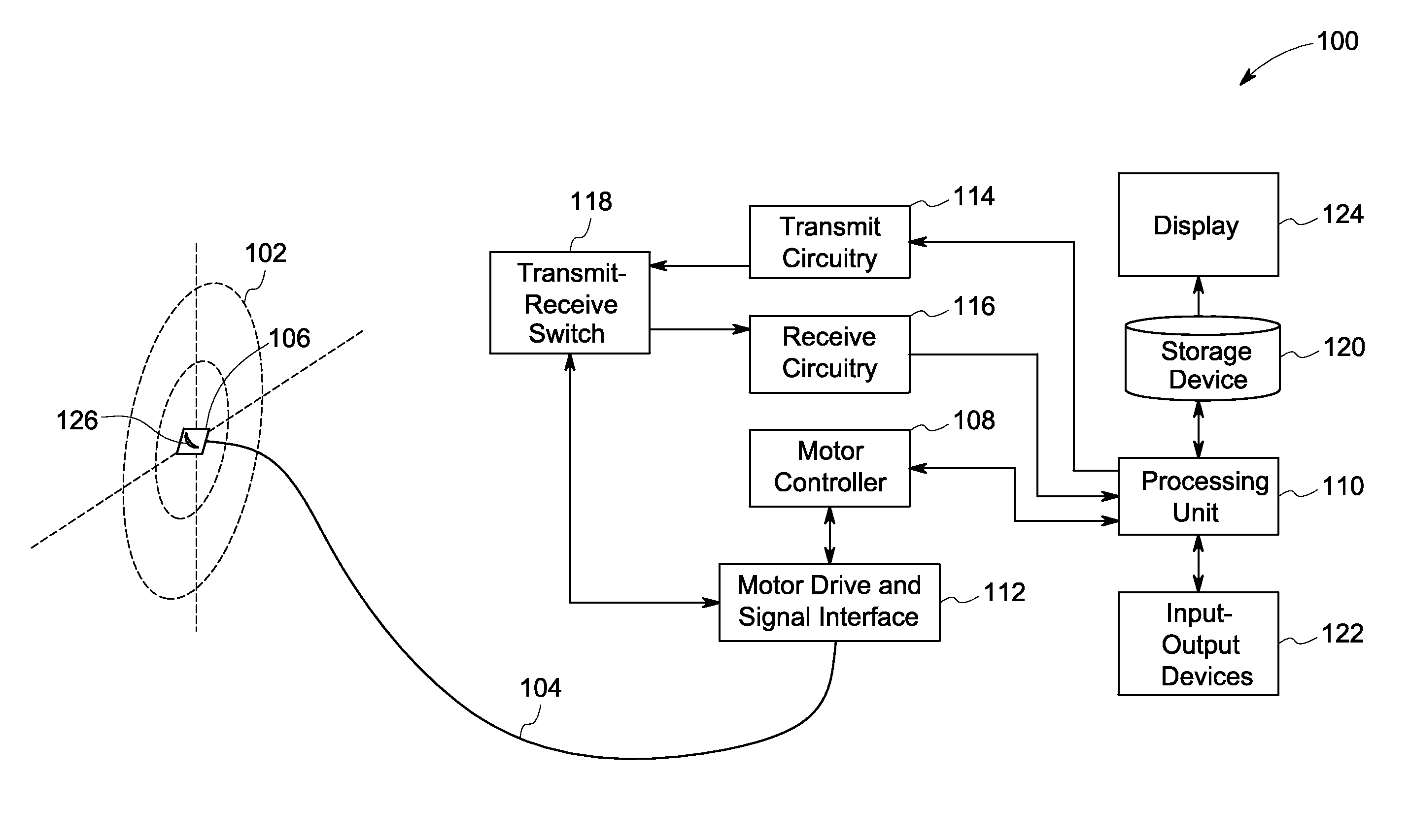
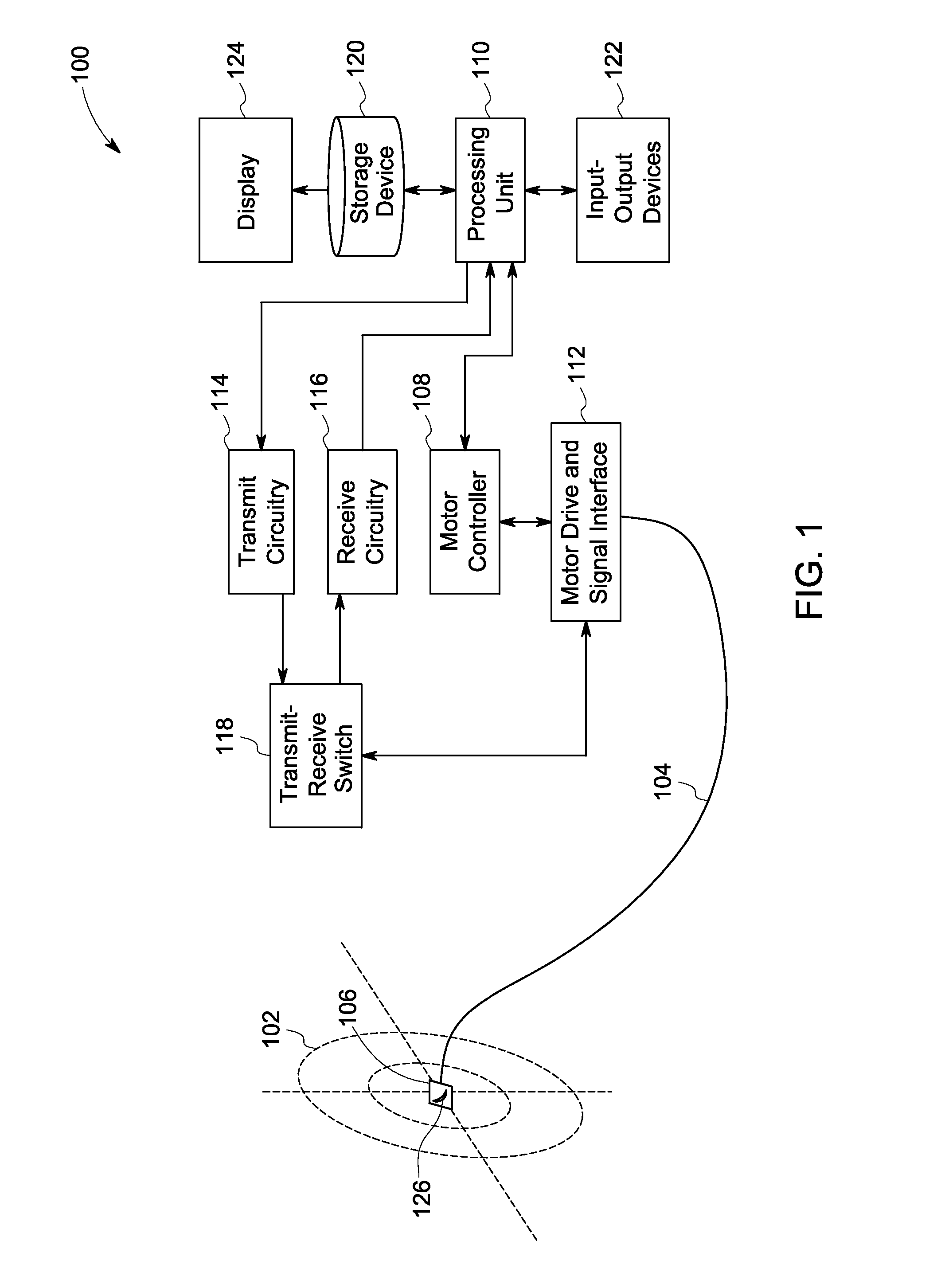
[0026]The following description presents intravascular ultrasound (IVUS) systems for reducing artifacts in ultrasound images using apodization functions for improved image quality, and methods of making and using such improved IVUS systems. The inventors of the present system realized the need for improved imaging quality during intravascular imaging. For example, it was realized that a metal strut of a coronary artery stent or calcium deposits formed in some diseased arteries may prove to be more reflective than most tissue structures and typically contributes to image artifacts when such strong reflectors are present in the sidelobe region of the ultrasound beam pattern for a particular imaging direction. Similarly, while imaging blood vessels, the media layer weakly reflects ultrasound energy as compared to the surrounding intima and adventia layers. In such scenarios, the net response of an unapodized aperture may be dominated by the reflectors in the sidelobe region. The bright...


PUM


Abstract

Embodiments of catheters, imaging systems and methods for intravascular ultrasound imaging are presented. At least one miniaturized transducer element adapted to be inserted into a vascular structure and configured to produce signals for use in generating one or more ultrasound images of a desired region within the vascular structure is used. Further, one or more apodizing structures operably coupled to the transducer element and configured to decrease the responsiveness of the transducer element at one or more boundaries of the transducer element with respect to the center of the transducer element are used. Particularly, the apodizing structures reduce sidelobe amplitude of an ultrasound beam profile in the region of interest, thereby generating improved ultrasound images.

Description

BACKGROUND[0001]Embodiments of the present technique relate generally to diagnostic imaging, and more particularly to systems and methods for reducing artifacts in intravascular ultrasound images for improved image quality.[0002]Ultrasonic imaging is a well-known imaging modality that employs ultrasonic acoustic energy generated by ultrasonic transducers. Particularly, ultrasound imaging is commonly used in industrial imaging for non-destructive evaluation and allows visualizing through various materials, components, or systems to detect corresponding features and characteristics. Ultrasound imaging has also found widespread use in many medical applications.[0003]Several conventional industrial ultrasound systems employ large single-element transducers, for example, having a size of about a few centimeters. Further, conventional ultrasound systems used for medical imaging often employ an array of transducer elements. These ultrasound systems process data received from the multiple t...

Claims


Application Information

Patent Timeline
IPC IPC(8): A61B8/12
CPCG01S7/52047G01S15/8922G01S15/894B06B1/0681A61B8/0891A61B8/4483A61B8/12G01S7/52079
Inventor RIGBY, KENNETH WAYNEMILLS, DAVID MARTINFAN, YING
Owner GENERAL ELECTRIC CO
Why Eureka
Try Eureka