
System and method for gas turbine inlet air heating

Inactive Publication Date: 2013-08-08
GENERAL ELECTRIC CO
View PDF10 Cites 8 Cited by
  • Summary
  • Abstract
  • Description
  • Claims
  • Application Information

AI Technical Summary

Benefits of technology

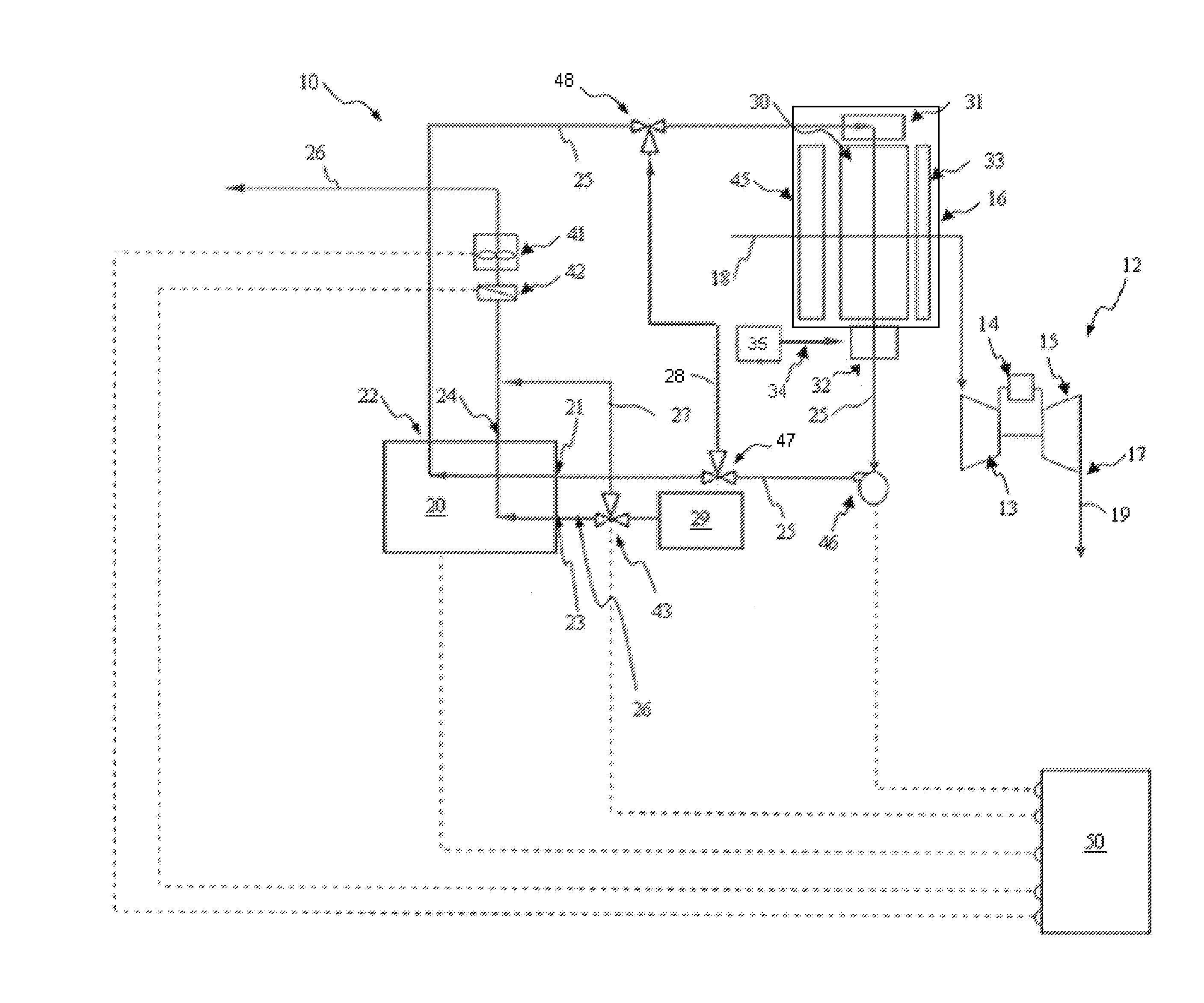
The patent describes a gas turbine system that improves efficiency and prevents ice buildup on the inlet and compressor inlet bellmouth. This system includes a heat exchanger that heats the inlet-air before it reaches the compressor, which reduces the mass flow and output of the gas turbine. This also lowers the temperature and extends the range of operation. Additionally, the system allows for the inlet air to be cooled or chilled for increased power output at baseload. This results in improved performance and reliability of the gas turbine system.

Problems solved by technology

However, baseload operation, though desired by operators, is not always feasible.
There may not be a demand in the energy market (electrical grid, or the like) for all of the energy generated at baseload.
Furthermore, partload operation tends to decrease the overall efficiency and increase the heat rate of the powerplant.
A gas turbine operating at a low ambient temperature may not be able to maintain ice-free inlet airflow.
Conventional approaches have focused on utilization of exhaust gas from the heat recovery steam generator, or addition of separate heating mechanisms such as inlet heating coils, which can be quite costly.
Additional separate systems within the gas turbine inlet contribute to system cost, complexity, and inlet pressure drop.

Method used


Image

  • System and method for gas turbine inlet air heating
  • System and method for gas turbine inlet air heating

Examples


Embodiment Construction

[0016]Reference now will be made in detail to embodiments of the invention, one or more examples of which are illustrated in the drawings. Each example is provided by way of explanation of the invention, not limitation of the invention. In fact, it will be apparent to those skilled in the art that various modifications and variations can be made in the present invention without departing from the scope or spirit of the invention. For instance, features illustrated or described as part of one embodiment, can be used with another embodiment to yield a still further embodiment. Thus, it is intended that the present invention covers such modifications and variations as come within the scope of the appended claims and their equivalents.

[0017]The present invention extends the turndown range by heating the inlet-air. In accordance with the present disclosure, the extended turndown range is from about 5% to about 70% of the maximum rated load of the gas turbine. Generally, the output (elect...


PUM


Abstract

In one embodiment of the present disclosure, a gas turbine system for part load efficiency improvement and anti-icing within the inlet and at the compressor inlet is described. The system includes a gas turbine having a compressor which receives inlet-air. A direct-contact heat exchanger heats the inlet-air before the inlet-air flows through the inlet and to the compressor. Heating the inlet-air reduces an output of the gas turbine and extends the turndown range, and avoids ice-forming conditions within the inlet and at the compressor inlet bellmouth. The direct-contact heat exchanger may also be configured to act as an evaporative cooler, air chiller, or use liquid dessicant.

Description

FIELD OF THE INVENTION[0001]The subject matter disclosed herein relates generally to gas turbines, and more specifically to methods and apparatus for operating gas turbines.BACKGROUND OF THE INVENTION[0002]The present invention relates to the operation of a gas turbine, and more particularly to systems and methods for anti-icing and part load efficiency improvement in a gas turbine.[0003]Turbomachines, such as gas turbines, aero-derivatives, or the like, commonly operate in a combined-cycle and / or cogeneration mode. In combined-cycle operation, a heat recovery steam generator, which generates steam, receives the exhaust-gas from the gas turbine; the steam then flows to a steam turbine that generates additional electricity. In a co-generation operation, a portion of the steam generated by the heat recovery steam generator is sent to a separate process requiring the steam.[0004]Combined-cycle and cogeneration plants are rated to generate the maximum amount of energy (mechanical, elect...

Claims


Application Information

Patent Timeline
IPC IPC(8): F02C7/143
CPCF02C7/047Y02E20/16Y02E20/14
Inventor ZHANG, JIANMINTOMEY, JAMES PATRICK
Owner GENERAL ELECTRIC CO
Learn More