Supercharge Your Innovation With Domain-Expert AI Agents!

Shallow trench isolation for device including deep trench capacitors

a capacitor and deep trench technology, applied in the field of shallow trench isolation (sti) regions, can solve the problems of power consumption of the dram, drop in performance, capacitance and amount of stored charge,

Inactive Publication Date: 2013-08-08
IBM CORP
View PDF2 Cites 4 Cited by
  • Summary
  • Abstract
  • Description
  • Claims
  • Application Information

AI Technical Summary

Benefits of technology

The patent text describes a method for making a shallow trench isolation (STI) region in a device that has trench capacitive elements. The method involves etching a direct adjacent to a metal plate or high-k dielectric, forming an oxide liner in the trench, and then adding an oxide fill to create the STI region. This technique also includes using a delay deposition technique to form a first fill layer and an oxidizing precursor to selectively oxidize the first fill layer and create the oxide fill in the STI trench. The technical effect of this method is to improve the reliability and performance of devices that have trench capacitive elements.

Problems solved by technology

Performance of DRAM arrays is related to the speed of data access and data writing, and to the power consumption of the DRAM.
The power consumption is dependent on the rate at which stored data need to be refreshed due to a gradual loss of stored charge from the storage capacitors through various leakage mechanisms or leakage currents.
As the memory density increases, the parasitic resistance rises, causing a drop in performance.
Similarly, the storage capacitance and amount of stored charge decreases for scaled down cells, forcing faster data refresh rates and increased power consumption.
Oxidized materials cause higher parasitic series resistance and structural defects in the adjacent substrate.
Higher series resistance reduces memory performance.
Structural defects result in electrical leakage between memory elements and may also interact with downstream thermal steps causing permanent wafer distortion and warping, which may degrade the quality of the lithography overlay between subsequent printed layers reducing yield of the manufacturing process.

Method used


Image

  • Shallow trench isolation for device including deep trench capacitors
  • Shallow trench isolation for device including deep trench capacitors
  • Shallow trench isolation for device including deep trench capacitors

Examples


Embodiment Construction

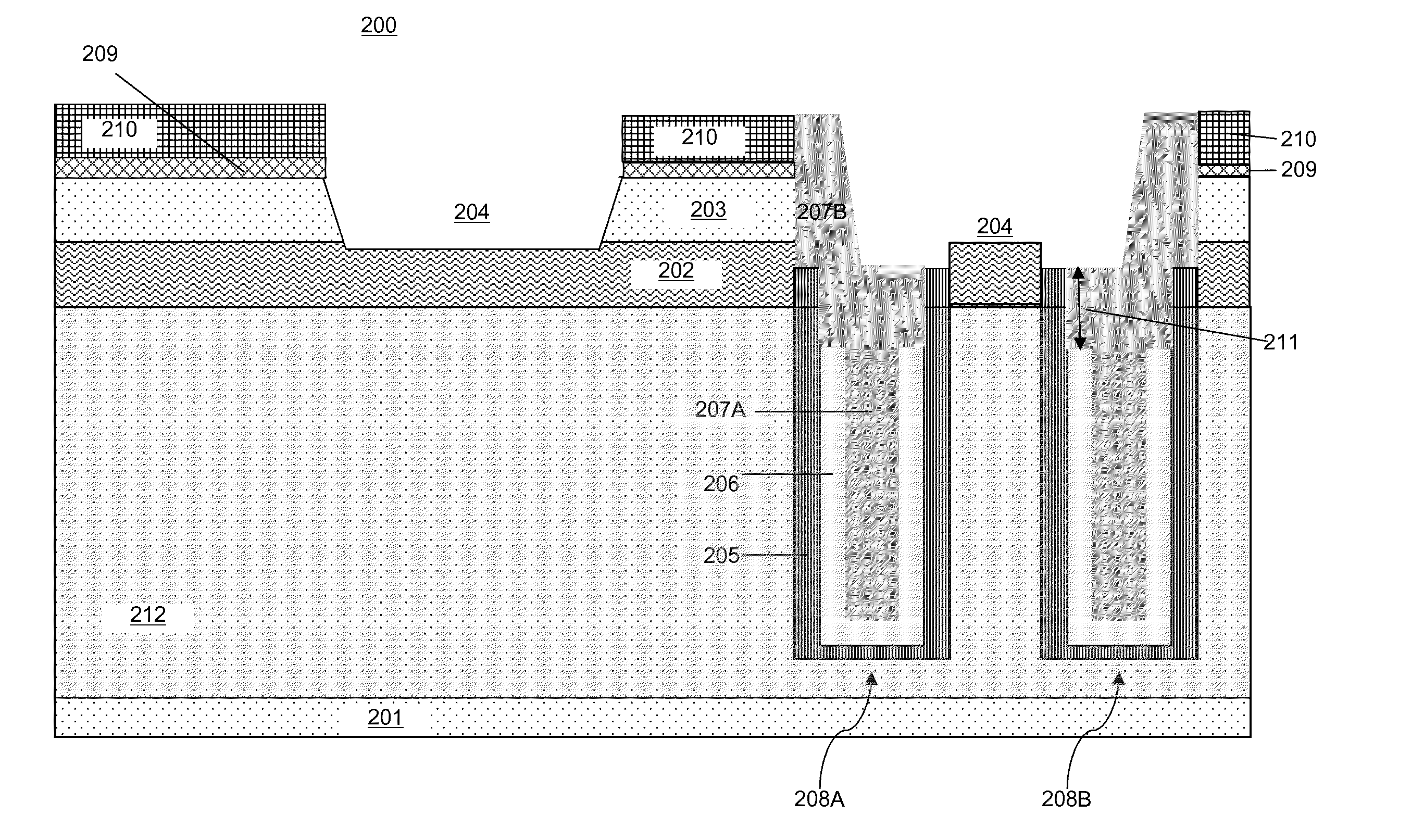
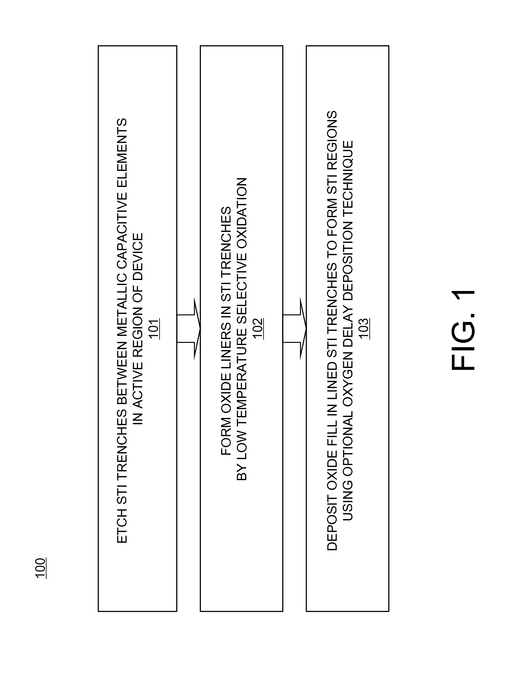
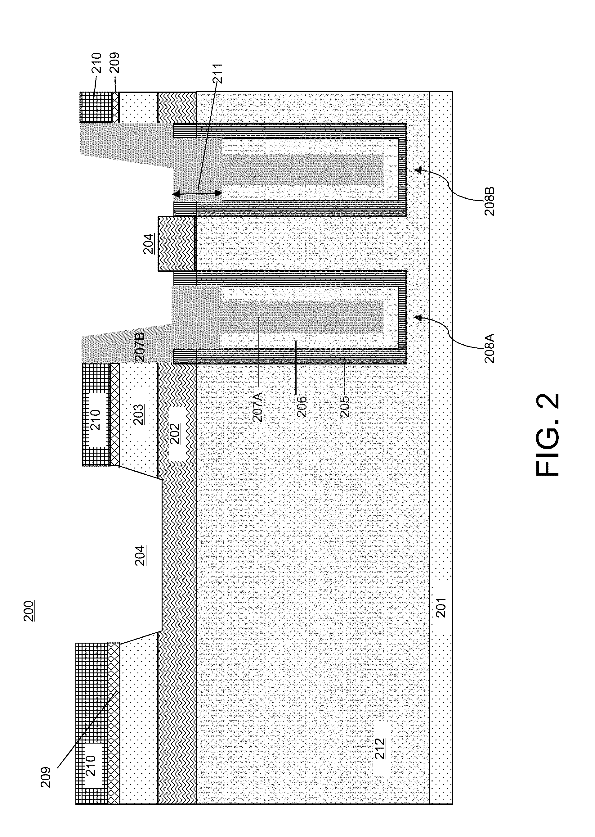
[0018]Embodiments of STI regions for a device including deep trench capacitors, and methods of forming STI regions for a device including deep trench capacitors, are provided, with exemplary embodiments being discussed below in detail. To continue DRAM scaling (i.e., further reduce area per unit memory cell, increase speed of memory cell operation, and maintain the amount of stored charge), the deep trench storage capacitors may include high-k deep trench node dielectric material and metal plate(s) that act as one or both electrodes of the storage capacitor. In a DRAM device that includes such capacitive elements with metal plate, oxidation of the metal plate material during STI region formation may be reduced by forming the STI liner using selective oxidation at a relatively low temperature. Such STI region formation techniques may also be used in conjunction with devices including deep-trench decoupling capacitors.

[0019]Selective oxidation for STI liner formation may be performed ...


PUM


Abstract

A method for formation of a shallow trench isolation (STI) in an active region of a device comprising trench capacitive elements, the trench capacitive elements comprising a metal plate and a high-k dielectric includes etching a STI trench in the active region of the device, wherein the STI trench is directly adjacent to at least one of the metal plate or high-k dielectric of the trench capacitive elements; and forming an oxide liner in the STI trench, wherein the oxide liner is formed selectively to the metal plate or high-k dielectric, wherein forming the oxide liner is performed at a temperature of about 600° C. or less.

Description

BACKGROUND[0001]This disclosure relates generally to the field of shallow trench isolation (STI) regions that are formed between electrical components on a wafer, and more particularly to STI regions for devices that include trench-based capacitors comprising high-k dielectric and metal plate.[0002]DRAM memory cells include two main components: a storage capacitor, which stores a charge, and an access transistor, which transfers charge to and from the capacitor. The communication between the storage capacitor and the access transistor is controlled by a select signal, commonly referred to as a word line, that connects one plate of the capacitor to a data line, commonly referred to as a bit line. The storage capacitor is typically located in a deep trench that is etched into a wafer comprising a semiconductor substrate. The deep trench design enables a large amount of charge to be stored in a relatively small chip surface area.[0003]Conventional DRAM arrays are organized so that mult...

Claims


Application Information

Patent Timeline
IPC IPC(8): H01L29/92H01L21/02
CPCH01L29/66181H01L21/76224H01L29/945H01L27/10861H10B12/038
Inventor FANG, SUNFEIGLUSCHENKOV, OLEGKIM, BYEONG Y.KRISHNAN, RISHIKESHYANG, DAEWON
Owner IBM CORP
Features
  • R&D
  • Intellectual Property
  • Life Sciences
  • Materials
  • Tech Scout
  • Unparalleled Data Quality
  • Higher Quality Content
  • 60% Fewer Hallucinations
Learn More