Enhanced sequential method for solving pressure/flow network parameters in a real-time distributed industrial process simulation system

a simulation system and network parameter technology, applied in fluid pressure control, program control, instruments, etc., can solve problems such as numerical unreliability, computational inefficiency, and inability to solve numerically reliable problems, and achieve high computational efficiency and conserve mass.

Active Publication Date: 2013-08-08
EMERSON PROCESS MANAGEMENT POWER & WATER SOLUTIONS
View PDF32 Cites 29 Cited by
  • Summary
  • Abstract
  • Description
  • Claims
  • Application Information

AI Technical Summary

Benefits of technology

[0015]A pressure and flow calculation technique can be used in a distributed or other process network simulation system that uses the sequential solving method to perform better or faster simulations of a process flow, especially with respect to process junction nodes at which flow either converges or diverges. The new pressure and flow variable determination technique uses a grouped node identification technique that identifies a local set of nodes for each junction node of the process network to use when solving for the pressure at the junction node, a grouped node iteration technique that uses the grouped set of nodes at each junction node to perform pressure calculations for the junction node, and a flow-based pressure calibration technique at each junction node to enable the system to perform highly accurate pressure and flow variable determination at each junction node in real-time.
[0016]In one case, a high fidelity distributed plant simulation technique performs real-time simulation or prediction of a process or plant network in a manner that uses a distributed set of simulation modules without requiring a centralized coordinator to coordinate the operation of the system, and in a manner that accurately solves mass and flow balances at the distributed sites in both steady state and dynamic conditions. In particular, the simulation system described herein may include any number of separate simulation modules, each of which implements first principle models or other types of models to model the operation of a plant component. The simulation system may include plant element simulation modules that model various plant components, such as tanks, heat exchangers, etc., and may include pipe simulation modules that model connection elements within the process or plant, such as pipes, etc., which operate to transport material flow from one plant element to another plant element.
[0020]Using this technique, a set of simulation modules is able to implement mass flow, pressure and / or temperature balancing equations that take into account the pressures, flow rates, and / or temperatures, etc., of upstream or downstream simulation modules, to thereby balance mass flows without the need of a central coordinator, but in a manner that is highly computationally efficient. In particular, each simulation module communicates with both upstream and downstream simulation modules and implements model equations that assure that mass flow is conserved across or between the upstream and downstream components. These simulation modules thereby eliminate the need for a central coordinator that tracks flow or that implements mass balancing equations for all of the distributed simulation modules. Still further, in the process of implementing mass flow balancing equations, the simulation modules provide feedback from downstream process element simulation modules to upstream process element simulation modules, so that changes in the downstream elements, such as changes in settings of flow shut-off valves, can be recognized and modeled in upstream elements, without the use of global variables within the simulation system and, again, without the use of a central coordinator. This feature avoids matrix singularities that can occur in a centralized simulation technique.
[0021]Still further, the simulation system implements a procedure that recognizes temporary mass imbalances in simulation modules, caused by, for example, transient or dynamic conditions, and deals with these transient mass imbalances in a manner that conserves mass over time and across multiple simulation modules, so as to provide an accurate simulation of the plant in the presence of dynamic changes, again without the need of a central coordinator. In particular, each simulation module associated with a non-mass storage device (e.g., a pipe) recognizes a disparity of mass flow between its input and its output as a result of a dynamic or a transient flow situation (i.e., a situation in which mass flow is increasing or decreasing), and communicates the amount of this mass imbalance to an upstream or a downstream simulation module. Over numerous cycles of the simulation system, mass imbalances detected by simulation modules associated with non-mass storage devices are thereby transferred to and are accumulated in simulation modules associated with mass storage devices (e.g., tanks), where the mass actually accumulates or depreciates. The simulation modules associated with the mass storage devices can accept and balance these transient masses over long term operation of the simulation system. This feature assures that mass is neither gained nor lost as a result of the modeling of mass flow through non-mass storage devices during dynamic changes in mass flow through these elements.

Problems solved by technology

None-the-less, only the most complex simulation systems are typically able to perform high fidelity simulation of a process plant because of the complex processes being implemented, the ever changing conditions within the plant including the degradation of devices over time and the presence of unaccounted for disturbance variables within the plant.
However, a major drawback associated with this simulation approach is that the physical models are complex and computationally expensive, especially when the system to be modeled is highly nonlinear and interactive.
Unfortunately, this technique is usually slow, is computationally inefficient, and is numerically unreliable.
However, efficient solving of the pressure-flow variables at each node or component of a distributed simulated network is an important part of real-time process simulation, as without it, the simulation will not be very accurate or useful.
Because all of the components being simulated are connected together in a network, the time required to complete the entire calculation can be challenging, especially when the network size is large.
There are many disadvantages of using this distributed simulation approach.
For example, the algorithms in these types of distributed systems may not efficiently deal with the case in which the number of sub-systems is large because, in such a situation, there is a heavy computational load on the server side.
In particular, the central coordinator must calculate and break the mass and energy balances at the transient stages, which places a high computational load on the central server, especially in a large system.
Of course, if the server has too heavy of a computational load, the simulation system slows down, which may make the simulation system impractical for use as a real-time simulator, i.e., one that is able to perform simulation calculations to model the operation of a process network in real time.
This disadvantage is especially prevalent when the size of the network being simulated is large, as the computational time needed for a simultaneous system grows exponentially as the number of calculated pressure nodes increases.
Another potential problem is that the available communication bandwidth may be insufficient.
In particular, at the synchronization point (i.e., at the central server), the communication load of the network may be huge, requiring a high hardware implementation cost.
The other shortcoming of this approach is that the entire structure is pre-built, which means that the solver may have difficulty in handling matrix singularities that can arise in certain situations.
For example, when two valves in a single straight flow path are both closed, the solver may not be able to directly determine the pressures in between these nodes, if the equations are not processed properly.
This problem can lead to a failure of the simulation system as a whole in certain process situations.
Moreover, due to the nature of this approach, the determination of the pressure and flow propagation through the network can be slow for a large-sized network.
If not handled properly, this slow propagation can degrade the degree of simulation fidelity.
These types of calculations can become complicated, however, when the flow paths of the network converge or diverge at a particular node.
In fact, if not performed correctly, the pressure and flow calculations performed for nodes that have converging or diverging flows in a distributed simulation network can quickly become inaccurate, leading to a sub-par simulation.

Method used


Image

  • Enhanced sequential method for solving pressure/flow network parameters in a real-time distributed industrial process simulation system
  • Enhanced sequential method for solving pressure/flow network parameters in a real-time distributed industrial process simulation system
  • Enhanced sequential method for solving pressure/flow network parameters in a real-time distributed industrial process simulation system

Examples


Embodiment Construction

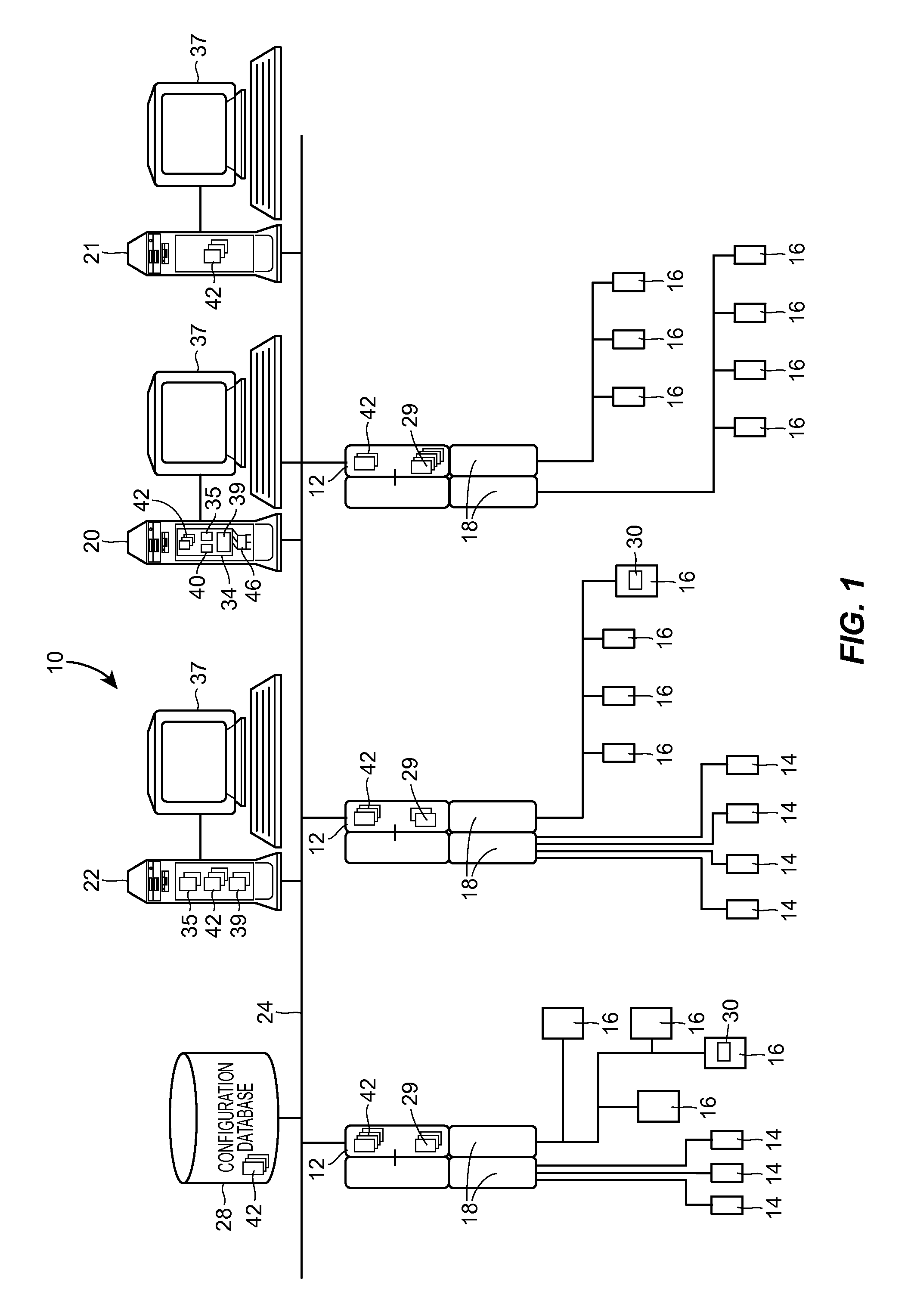
[0038]Referring now to FIG. 1, an example distributed control network for a plant 10, such as that associated with a power generation plant, an industrial manufacturing plant, a processing plant, etc. is illustrated at an abstract level of detail. The plant 10 includes a distributed control system having one or more controllers 12, each of which is connected to one or more field devices 14 and 16 via input / output (I / O) devices or cards 18 which may be, for example, Fieldbus interfaces, Profibus® interfaces, HART® interfaces, standard 4-20 ma interfaces, etc. The controllers 12 are also coupled to one or more host or operator workstations 20, 21 and 22 via a data highway 24 which may be, for example, an Ethernet link. A database 28 may be connected to the data highway 24 and operates as a data historian to collect and store parameter, status and other data associated with the controllers 12 and field devices 14, 16 within the plant 10. Additionally or alternatively, the database 28 m...


PUM


Abstract

A pressure and flow calculation technique can be used in a distributed process network simulation system that uses the sequential solving method to perform better or faster simulations of a process flow, especially with respect to process junction nodes at which flow either converges or diverges. The pressure and flow variable determination technique uses a grouped node identification technique that identifies a local set of nodes for each junction node of the process network to use when solving for the pressure at the junction node, a grouped node iteration technique that uses the grouped set of nodes at each junction node to perform iterative pressure calculations at the junction node, and a flow-based pressure calibration technique at each junction node to enable the system to perform highly accurate pressure and flow variable determination at each junction node in real-time.

Description

TECHNICAL FIELD[0001]The present invention relates generally to simulating the operation of power generation plants, industrial manufacturing plants, processing plants and other types of process plants and, more particularly, to a system and method for solving pressure / flow parameters in real-time in a distributed process network simulation system.DESCRIPTION OF THE RELATED ART[0002]Distributed process control systems, like those typically used in power generation, chemical manufacturing, petroleum processing, industrial manufacturing or other types of plants, typically include one or more controllers communicatively coupled to a plurality of field devices via analog, digital, combined analog / digital, or wireless buses. The field devices, which may be, for example, valves, valve positioners, switches, transmitters (e.g., temperature, pressure, level and flow rate sensors), burners, heat exchangers, furnaces, etc. are located within the plant environment and perform process functions...

Claims


Application Information

Patent Timeline
Patent Type & Authority Applications(United States)
IPC IPC(8): G06F17/11G06G7/50
CPCG05B17/02G05D16/2073G05B2219/2213G05B2219/2203G05D7/0688G05B2219/2214G05D16/20G05D16/2066G06F17/5018G06F17/5036G05D16/2006G05B19/41885G06F30/23G06F30/367
Inventor CHENG, XUWEN, CHENGTAO
Owner EMERSON PROCESS MANAGEMENT POWER & WATER SOLUTIONS
Why Eureka
Try Eureka