Modular hemodialysis system

a hemodialysis and module technology, applied in the field of pathological conditions system and method treatment by hemodialysis and hemofiltration, can solve the problems of dialysis treatment, insufficient clearance function of individuals with kidney disease to prevent urea from reaching unsafe levels, and inability to emulate the continuous function of the natural renal system

Active Publication Date: 2013-08-22
MOZARC MEDICAL US LLC
View PDF13 Cites 147 Cited by
  • Summary
  • Abstract
  • Description
  • Claims
  • Application Information

AI Technical Summary

Benefits of technology

[0079]In any embodiment, a control pump adds fluid from a control reservoir to a first or second dialysis circuit in an influx direction via a conduit or removes fluid from the first or second dialysis circuit to the control reservoir in an efflux direction via the conduit, and intermittently switching the control pump between the efflux direction to move fluid across the dialysis membrane from the ex

Problems solved by technology

Individuals with kidney disease have insufficient clearance function to prevent urea from reaching unsafe levels.
Although effective at removing wastes from blood, dialysis treatments are administered intermittently and therefore do not emulate the continuous function of the natural renal system.
Due to the time-intensive requirements of in-patient dialysis treatment, many patients eventually elect to forego treatment on this basis alone.
Moreover, due to the limitations and inconvenience of existing hemodialysis equipment, implementation of more frequent treatment is costly and patient compliance is expected to be difficult despite the possibility that high morbidity observed for End Stage Renal Disease (ESRD) patients receiving kidney replacement therapy may be the result of factors other than urea buildup in the blood.
Due to the large volume of dialysate needed and specialized water hookup and disposal facilities required for traditional dialysis treatment, traditional hemodialysis treatment is limited to specialized clinical facilities.
However, the amount of dialysate fluid subject to regeneration is typically in excess of 6 L making portability of the system during treatment impractical.
However, the regenerated dialysate produced by REDY systems is subject to va

Method used


Image

  • Modular hemodialysis system
  • Modular hemodialysis system
  • Modular hemodialysis system

Examples


Embodiment Construction

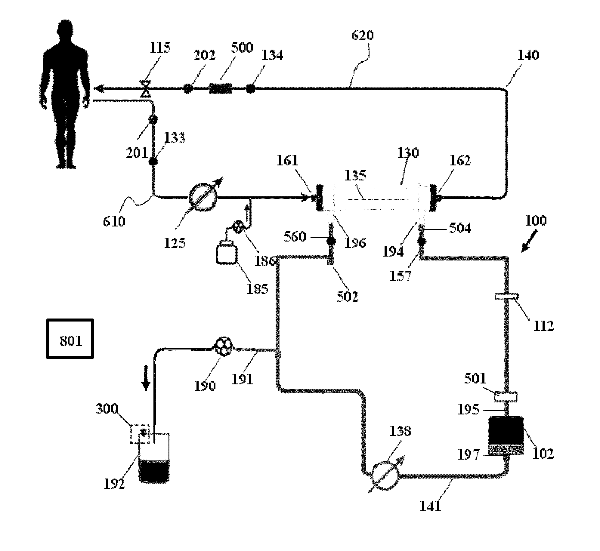
[0107]The present invention provides for more frequent removal of accumulated fluid in individuals with End Stage Renal Disease (ESRD). Subjects with ESRD have a reduced ability to eliminate excess fluid from the body leading to a significant degree of fluid retention in body tissues. However, the volume of the blood does not vary by a significant amount from the approximately 5 L volumes for adult humans. Excess fluid can be removed from the body by ultrafiltration of the blood by the present invention. The rate at which fluid can be removed from body tissues by ultrafiltration is limited due to the lag time for replacement or migration of fluid from the body compartment containing the body tissue fluid to the blood. Hence, removal of excess body tissue fluid requires a relatively low rate of ultrafiltration for net fluid removal over an extended period of time. The present invention provides for performing ultrafiltration for fluid removal on a more frequent basis than treatments ...


PUM

PropertyMeasurementUnit
Fractionaaaaaaaaaa
Molar massaaaaaaaaaa

Abstract

Apparatuses, systems, and methods for the performance of kidney replacement therapy having or using a dialyzer, control components, sorbent cartridge, and fluid reservoirs configured to be of a weight and size suitable to be worn or carried by an individual requiring treatment are disclosed. The system has a controlled compliance dialysis circuit, where a control pump controls the bi-directional movement of fluid across a dialysis membrane. A first sorbent cartridge is provided for use in a portable treatment module having activated carbon and zirconium oxide. The system also provides for the monitoring of an inlet and outlet conductivity of a sorbent cartridge containing urease to provide a facility to quantify or monitor the removal of urea by a detachable urea removal module.

Description

FIELD OF THE INVENTION[0001]The invention relates to systems and methods of treatment by hemodialysis and hemofiltration for pathological conditions such as End Stage Renal Disease (ESRD). The systems and methods include a portable system having a dialyzer, control components, and a sorbent cartridge for dialysate configured to include an activated carbon sorbent material. The disclosure further relates to the treatment of Chronic Kidney Disease (CKD) through methods and apparatuses that allow an individual to remain ambulatory during treatment for the removal of uremic waste species and phosphates and to employ a base station module for the periodic removal of urea.BACKGROUND[0002]Urea is a neutral, polar and water miscible compound that is not readily separated from an aqueous solution, and is the main product of nitrogen metabolism by the body. In individuals with normal kidney function, urea is produced by the liver and accumulates in the blood to the level of few millimoles per...

Claims


Application Information

Patent Timeline
IPC IPC(8): A61M1/16
CPCA61M1/16A61M1/1696A61M2205/3317A61M2205/3324A61M2205/3334A61M2205/50A61M2230/207A61M1/1607A61M1/1609A61M1/3609A61M2205/15A61M1/3612G16H40/63G16H20/40
Inventor KELLY, THOMAS D.LYU, SUPINGPUDIL, BRYANT J.MEYER, THOMAS E.
Owner MOZARC MEDICAL US LLC
Why Eureka
Try Eureka