

Thermal collector tube, thermal collector and concentrated solar power generation system
a technology of solar energy generation system and collector tube, which is applied in the field of thermal collector tube, thermal collector tube, and concentrated solar power generation system, can solve the problems of increasing heat loss
- Summary
- Abstract
- Description
- Claims
- Application Information
AI Technical Summary
Benefits of technology
Problems solved by technology
Method used
Image

Examples
first embodiment
[0032]Hereinafter, a first embodiment, which is an embodiment of the invention, will be described with reference to the accompanying drawings.
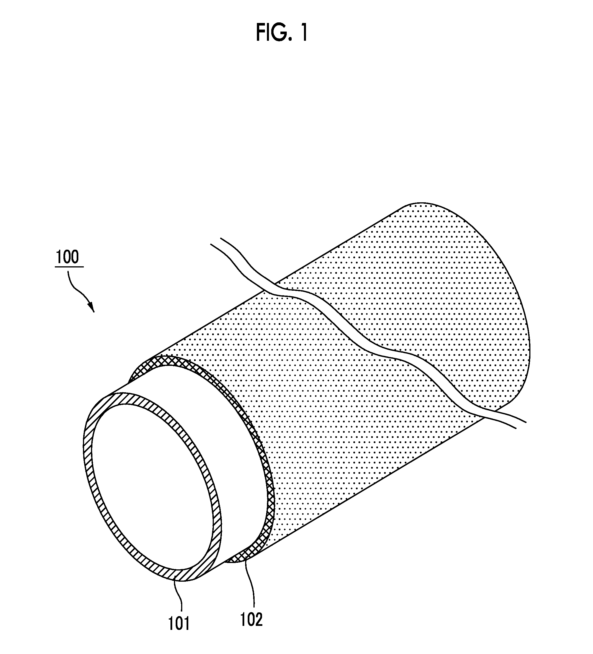
[0033]FIG. 1 is a perspective view illustrating the configuration of a thermal collector tube according to the first embodiment of the invention.
[0034]As illustrated in FIG. 1, the thermal collector tube 100 according to the present embodiment has a main body portion 101 and a coating layer 102 formed on the outside surface of the main body portion.
[0035]In FIG. 1, the locations of the main body portion 101 and the coating layer 102 are deviated in order to explain the structure of the thermal collector tube 100 in an easily understandable manner; however, strictly, the coating layer 102 is formed on the entire outside surface of the main body portion 101.
[0036]The main body portion 101 has a horizontally long shape, and is configured so as to be capable of housing a heat medium therein. Specifically, the main body portion is a tube having a r...
example 1
[0076]A glass tube made of silica glass was used as the main body portion 101. The glass tube was obtained by cutting a cylinder having a thickness of 2 mm and a diameter of 100 mm into a length of 100 mm.
[0077](Formation of the Coating Layer)
[0078]Next, MnO2 powder (65 wt %) as the crystalline inorganic material, CuO powder (5 wt %) and BaO—SiO2 glass powder (30 wt %) as the amorphous inorganic material were dry-mixed so as to prepare a powder mixture, 100 parts by weight of water was added to 100 parts by weight of the powder mixture, and the components were wet-mixed using a ball mill, thereby preparing a slurry (coating material).
[0079]A coating process, in which this slurry was coated toward the outer surface of the glass tube through spray coating was carried out.
[0080]After that, the glass tube having the coated layer formed through spray coating was dried at 100° C. for two hours, and a firing process, in which the glass tube was heated and fired at 700° C. in the air for on...
examples 2 to 7
[0088]Regarding the material of the coating layer 102, the proportion of the amorphous inorganic material and the type of the crystalline material were set as described in Table 1 respectively. That is, MnO2 and Fe3O4 were adjusted to 30 wt % in Example 2, MnO2 and CuO were set to 70 wt % in Example 3, MnO2 and Fe3O4 were set to 10 wt % in Example 4, mullite was set to 30 wt % in Example 5, MnO2 and CuO were set to 90 wt % in Example 6, and Al2O3 was set to 30 wt % in Example 7. Thermal collector tubes 100 were manufactured in the same manner as in Example 1 using the above materials.
[0089]Here, the proportion of the crystalline material was the proportion obtained by subtracting the proportion of the amorphous inorganic material, which is described in Table 1, from 100%, and, in a case in which the crystalline material is made up of two materials, the composition was set to MnO2:CuO=65 wt %:5 wt %, MnO2:Fe3O4=65 wt %:5 wt %. Meanwhile, as the amorphous inorganic material, the same ...
PUM
| Property | Measurement | Unit |
|---|---|---|
| softening temperature | aaaaa | aaaaa |
| temperature | aaaaa | aaaaa |
| temperature | aaaaa | aaaaa |
Abstract
Description
Claims
Application Information