Method & apparatus for laser welding with mixed gas plasma suppression

a plasma suppression and laser welding technology, applied in welding apparatus, metal-working equipment, manufacturing tools, etc., can solve the problems of loss of penetration, unstable plasma, and simple substitution of processing steps and materials, so as to enhance weld penetration, improve plasma suppression, and improve plasma suppression

Active Publication Date: 2013-09-12
DACKSON CHRISTOPHER
View PDF10 Cites 20 Cited by
  • Summary
  • Abstract
  • Description
  • Claims
  • Application Information

AI Technical Summary

Benefits of technology

[0046]An advantage of the present invention is mixing pure incoming plasma suppression gases externally as the gases exit from the nozzle tip and flow across the beam prior to impingement of the beam upon the substrate surface.
[0047]Another advantage of the present invention is provision of an externally mixed gas for improved suppression of plasma during laser welding, which further enhances weld penetration.
[0048]A further advantage of the present invention is improved plasma suppression by relatively simple and inexpensive means that quickly returns acquisition cost, while easily retrofitting existing laser weld

Problems solved by technology

Plasma that is generated by the ionization of metal vapor coming from the component and the surrounding atmosphere can interfere with the beam energy reaching the component, resulting in a loss of penetration.
Such alternative methods are highlighted here to illustrate that simple substitution of processing steps and materials do not readily translate from one welding method to another because the methods are inherently different.
The application states that without the secondary orifice arrangement, the plasma can become unstable.
The approach is believed t

Method used


Image

  • Method & apparatus for laser welding with mixed gas plasma suppression
  • Method & apparatus for laser welding with mixed gas plasma suppression
  • Method & apparatus for laser welding with mixed gas plasma suppression

Examples


example

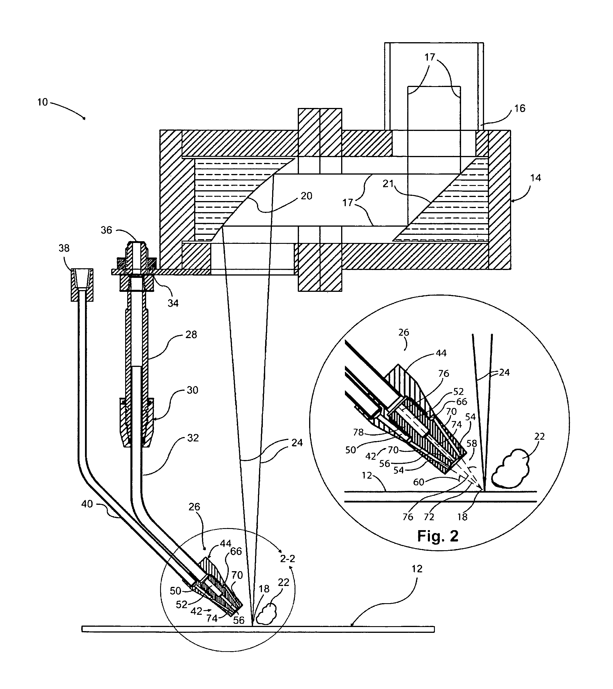
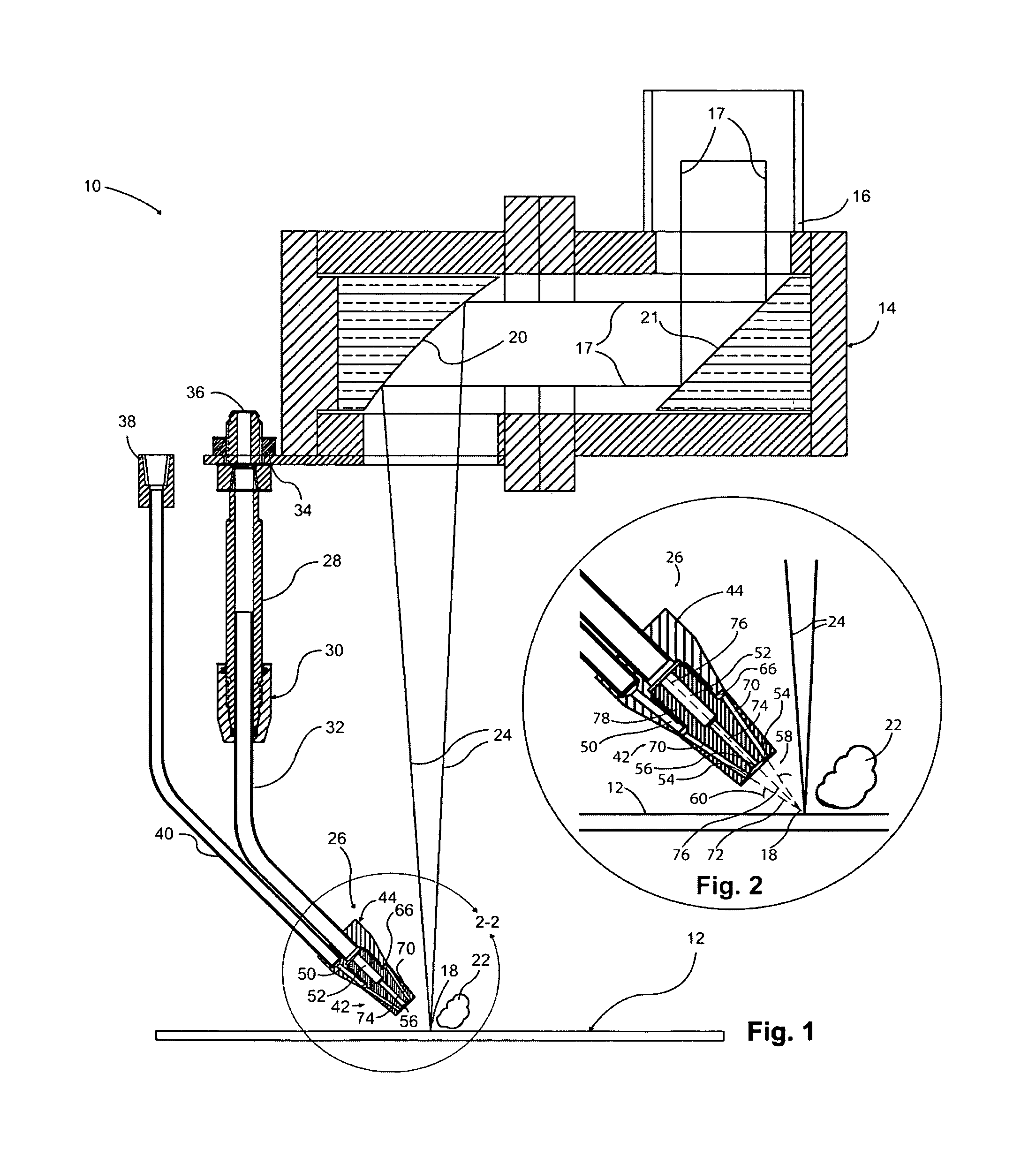
[0072]The gas economy and weld penetration improvements enabled by Applicant's invention have been demonstrated in actual laser welding of mild carbon steel, as well as stainless steel. As marked, the metallographic sample of carbon steel depicted in FIG. 14 reflects a weld penetration depth of 9.8018 mm with Applicant's externally mixed plasma suppression gases CO, at 10 SCFH plus Argon at 20 SCFH supplied to a dual gas nozzle (FIG. 1) of the present invention. By comparison, FIG. 15 shows a weld penetration into carbon steel of 9.102 mm (marked) using helium alone at a flow rate of 60 SCFH supplied through tube 32, that is, without use of Applicant's dual gas delivery system. A power of 6.0 kW and 1.0 meter per minute feed rate were set in each case. This translates to an improvement of 8% in weld penetration, by practice of the Applicant's invention. It was generally observed in welding mild carbon steel that Helium at 50 to 60 SCFH can be replaced by CO2 at 5 to 10 SCFH plus Arg...


PUM

PropertyMeasurementUnit
Angleaaaaaaaaaa
Angleaaaaaaaaaa
Angleaaaaaaaaaa

Abstract

Machinery and process are disclosed for laser welding. A beam is generated and focused on a discrete work surface, with a distinctive nozzle provided for delivering plasma suppression gas toward the surface. The nozzle has first and second inlets for receiving first and second sources of different plasma suppression gases, respectively. The nozzle has first and second outlets in fluid communication with the first and second inlets, respectively, together directing an externally mixed stream of the gases from the nozzle at an angle of incidence of 35 degrees to 50 degrees relative to the surface to impinge upon the generated plasma. The impinging stream intersects the beam at or above the surface, as the mixed gases are deflected across the beam. The invention saves on helium costs and demonstrably increases weld penetration.

Description

CROSS-REFERENCE TO RELATED APPLICATION[0001]NoneTECHNICAL FIELD[0002]The present invention relates generally to a device and method for delivery of plasma suppression gas in a welding apparatus, and more particularly to a laser welding apparatus.BACKGROUND[0003]The laser is a device that generates a nearly collimated beam of light energy. When its beam is directed, manipulated and focused with respect to a workpiece, it has a consistency that makes it ideally suited for automated processing. The laser beam delivery system is comprised of components that accept the beam from the laser (and enclose it), direct it to the workpiece, and condition it into a useable form of energy. These generally include, for CO2 lasers: beam bending mirrors, interconnecting beam guard tubes, and may include a beam collimator for moving beam or long beam delivery systems in a reflective system. In addition, the system requires a focus module with a focusing optic, and a plasma suppression gas delivery no...

Claims


Application Information

Patent Timeline
IPC IPC(8): B23K26/14
CPCB23K26/1476B23K26/24B23K26/125B23K26/14B23K26/1452B23K26/1458B23K26/1464B23K26/1405B23K26/1462B23K26/142B23K26/1438
Inventor DACKSON, CHRISTOPHER
Owner DACKSON CHRISTOPHER
Why Eureka
Try Eureka