Power converter for driving switched reluctance motor

a technology of power converter and reluctance motor, which is applied in the direction of motor/generator/converter stopper, dynamo-electric converter control, instruments, etc., can solve the problems of high cost, large capacity, and difficult for the power converter to increase the phase number, so as to improve the reliability of the power converter, the effect of sufficient torque, and the improvement of magnetization speed and demagnetization speed

Inactive Publication Date: 2013-09-12
TANAKA SHOUICHI
View PDF1 Cites 10 Cited by
  • Summary
  • Abstract
  • Description
  • Claims
  • Application Information

AI Technical Summary

Benefits of technology

[0023]According to another preferred embodiment, the dual Miller mode is selected, when either of the two bridges has a trouble. Therefore, the reliability of the power converter is improved. According to another preferred embodiment, the dual Miller mode is selected, when a rotation speed of the SRM is a high speed area. Therefore, the SRM produces a sufficient torque in the high speed area even though the back electromagnetic force (EMF) is increased in the high speed area.
[0024]According to another preferred embodiment, the magnetizing mode and the demagnetizing mode of one bridge are executed alternately with a predetermined frequency in the dual Miller mode. Therefo

Problems solved by technology

However, it is known for the SRM to have drawbacks such as acoustic noise, vibration, torque ripples and a torque/weight ratio in comparison with a popular permanent magnet synchronous motor.
However, it is not easy for the power converter to increase the phase number because of a cost of the multi-phase power converter.
However, The full-bridge power converter requires four switches per phase.
However, the

Method used


Image

  • Power converter for driving switched reluctance motor
  • Power converter for driving switched reluctance motor
  • Power converter for driving switched reluctance motor

Examples


first embodiment

A First Embodiment

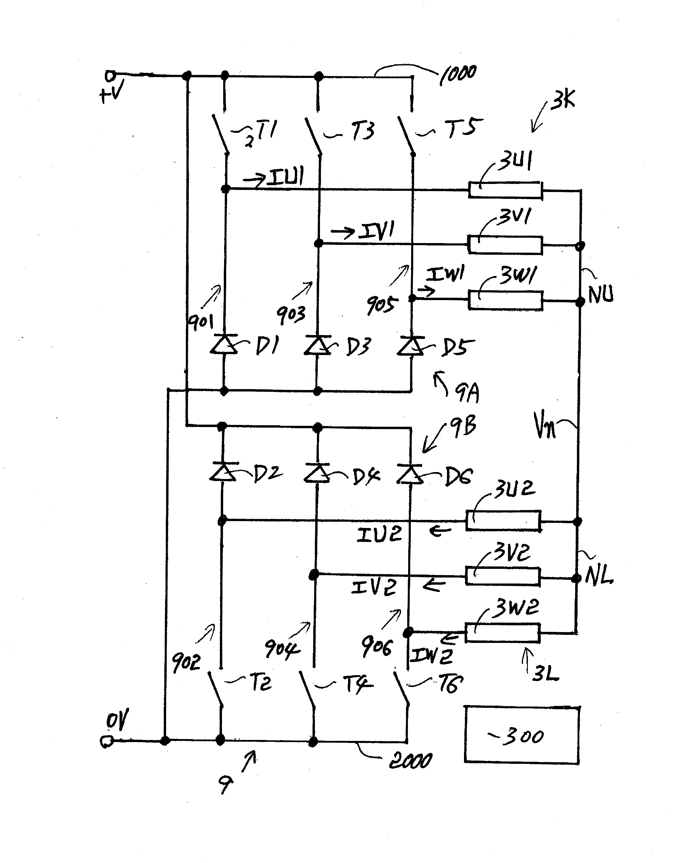
[0072]The first embodiment is explained referring to FIGS. 6-21. FIG. 6 is a circuit topology configuration showing a six-phase power converter 9 for driving a six-phase SRM having six phase windings 3U1-3W2 shown in FIGS. 7 and 8. FIG. 7 is a schematic cross-section showing one example of the six-phase SRM of 12 / 14 type. FIG. 8 is a schematic development showing a stator 2 having six stator poles 20 and a rotor 4 having seven rotor poles 40. The SRM shown in FIG. 7 has two sets of six phase windings 3U1-3W2 wound respectively on the six stator poles 20 in turn. The six phase windings 3U1-3W2 consist of the U1-phase windings 3U1, the U2-phase winding 3U2, the V1-phase windings 3V1, the V2-phase winding 3V2, the W1-phase windings 3W1 and the W2-phase winding 3W2.

[0073]The power converter 9 consists of an upper bridge 9A, a lower bridge 9B and a controller 300. The upper bridge 9A has a U1-phase leg 901, a V1-phase leg 903 and a W1-phase leg 905. The U1-phase leg 901...

second embodiment

A Second Embodiment

[0096]The second embodiment is explained referring to FIGS. 18-32. FIG. 18 is a circuit topology configuration showing another six-phase power converter 9. The power converter 9 shown in FIG. 18 is essentially same as power converter 9 shown in FIG. 5 except a neutral voltage controller 9C shown in FIG. 18. The neutral voltage controller 9C shown in FIG. 18 consists of a connection switch T9, a current-absorbing leg 907 and a current-supplying leg 908.

[0097]The connection switch T9 connects the upper neutral point NU of the upper three-phase winding 3K to the lower neutral point NL of the lower three-phase winding 3L. The current-absorbing leg 907 has a current-absorbing diode D7 and a current-absorbing switch T7 connected in series. A cathode electrode of the current-absorbing diode D7 is connected to the high potential DC link line 1000. An anode electrode of current-absorbing diode D7 is connected to upper neutral point NU. The current-absorbing switch T7 conne...

third embodiment

A Third Embodiment

[0140]The third embodiment is explained referring to FIG. 41. FIG. 41 is a circuit topology configuration showing a four-phase power converter 9 for driving a four-phase SRM. The power converter 9 shown in FIG. 41 is essentially same as power converter 9 shown in FIG. 18. However, upper bridge 9A has only two legs 901 and 903 for driving X-phase winding 3X and Z-phase winding 3Z. Similarly, lower bridge 9B has only two legs 902 and 904 for driving Y-phase winding 3Y and T-phase winding 3T.

[0141]Four-phase power converter 9 shown in FIG. 41 can have the asymmetric bridge mode, the accelerated bridge mode and the dual Miller mode like the second embodiment explained above. Further, the power converter 9 shown in FIG. 41 is capable of supplying four-phase currents IX, IY, IZ and IT having the half rectified sinusoidal waveforms each. Moreover, the power converter 9 shown in FIG. 41 is capable of supplying each phase currents being equal to a sum of a DC current compon...


PUM


Abstract

An upper bridge of the power converter drives a half of phase windings. A lower bridge of the power converter drives the other half of the phase windings. For example, an upper neutral point of a star-connected upper phase windings is connected to a lower neutral point of a star-connected lower phase windings via a connection switch. A current-absorbing leg absorbs a current from the upper neutral point. A current-supplying leg supplies a current to the lower neutral point. Preferably, the power converter has an asymmetric bridge mode, a dual Miller mode and an accelerated bridge mode by means of switching the connection switch, the current-absorbing leg and the current-supplying leg.

Description

CROSS-REFERENCE TO RELATED APPLICATION[0001]This application claims benefit under 35 U.S.C. 119 of JP2012-048906 filed on Mar. 6, 2012, the title of TRANSVERSE FLUX MACHINE APPARATUS, JP2012-85172 filed on Apr. 4, 2012, the title of POWER CONVERTER FOR DRIVING SWITCHED RELUCTANCE MOTOR, JP2012-90645 filed on Apr. 12, 2012, the title of POWER CONVERTER FOR DRIVING SWITCHED RELUCTANCE MOTOR and JP2012-95387 filed on Apr. 19, 2012, the title of POWER CONVERTER FOR DRIVING SWITCHED RELUCTANCE MOTOR, the entire content of which is incorporated herein reference.BACKGROUND OF INVENTION[0002]1. Field of the Invention[0003]The present invention relates to a power converter for driving a switched reluctance motor, in particular a power converter for driving a switched reluctance motor having phase windings of four or six or more than six of even number.[0004]2. Description of the Related Art[0005]It is known for a switched reluctance motor (SRM) to have many advantages for a variable-speed ap...

Claims


Application Information

Patent Timeline
IPC IPC(8): H02P6/14H02M3/155H02M7/48H02P25/08
CPCH02P25/22H02P25/088H02P25/085H02P25/092H02P25/098
Inventor TANAKA, SHOUICHI
Owner TANAKA SHOUICHI
Why Eureka
Try Eureka