Scanning display device and speckle reduction method
- Summary
- Abstract
- Description
- Claims
- Application Information
AI Technical Summary
Benefits of technology
Problems solved by technology
Method used
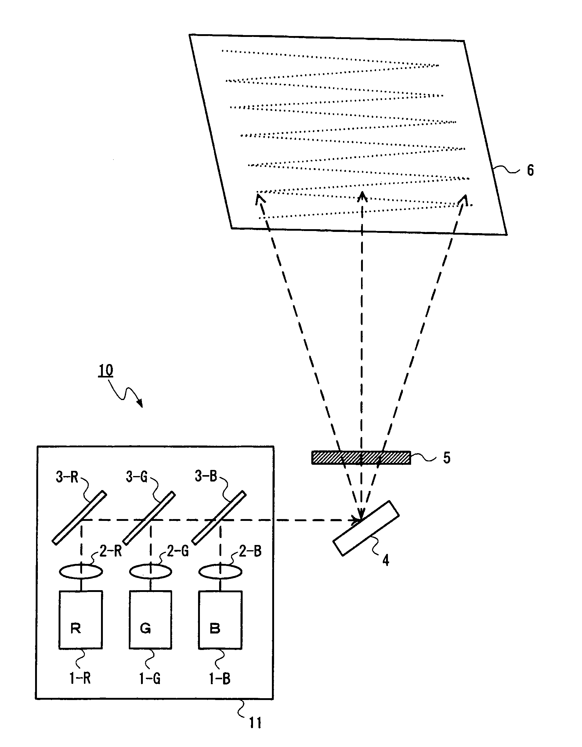
Image

Examples
first example
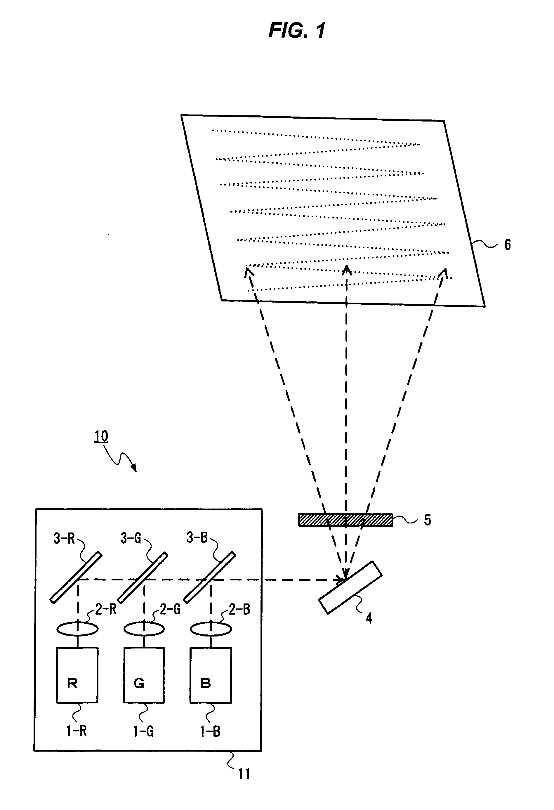
[0101]A first example of the invention is now described. This example is the exemplification of use of the depolarizer 5A in the embodiment.
[0102]First, an antireflection film is formed over one surface of each of the transparent substrates 51 and 52 that are made from a quartz glass substrate having a thickness of 0.3 mm. Next, polyimide is applied over the other side surface of each substrate covered with the antireflection film. The substrates are then baked and linearly rubbed in a single direction, thereby forming alignment layers (not shown).
[0103]Next, a wedge-shaped empty cell is fabricated by sandwiching a glass plate 59 having a thickness of 300 micrometers at a depth of 18 mm inside from one side of the substrates in such a way that, in the transparent substrates 51 and 52 on which the alignment layers are respectively formed, the alignment layers face inside and that rubbing directions of the alignment layers become anti-parallel to each other and that an angle between t...
second example
[0106]A second example of the invention is now described. This example is another exemplification of use of, in the embodiment, the depolarizer 5A that has a polarized light distribution which differs from that exhibited in the first example.
[0107]First, an antireflection film is formed over one surface of each of the transparent substrates 51 and 52 that are made from a quartz glass substrate having a thickness of 0.3 mm. Next, polyimide is applied over the other side surface of each substrate covered with the antireflection film. The polyimide films are then baked and linearly rubbed in a single direction, thereby forming alignment layers (not shown).
[0108]Next, a wedge-shaped empty cell is fabricated by sandwiching the glass plate 59 having a thickness of 150 micrometers at a depth of 18 mm inside from one side of the substrates in such a way that, in the transparent substrates 51 and 52 on which the alignment layers are respectively formed, the alignment layer surfaces face insi...
third example
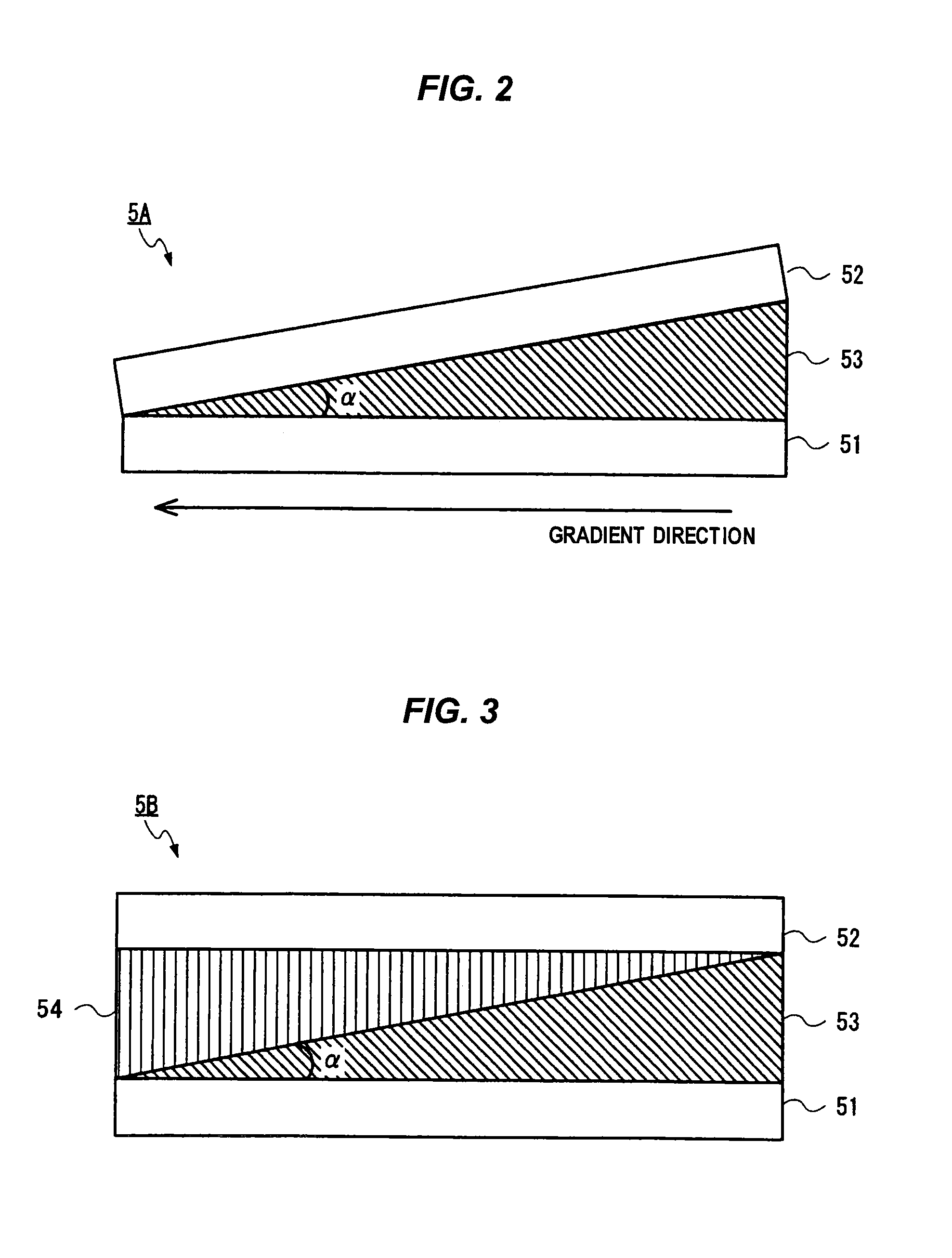
[0112]A third example of the invention is now described. This example is the exemplification of use of the depolarizer 5B in the embodiment.
[0113]First, an antireflection film is formed over one surface of each of the transparent substrates 51 and 52 that are made from a quartz glass substrate having a thickness of 0.3 mm. A gradient structure having a gradient angle of about 0.96 degree is fabricated, on the other side surface of the transparent substrate 52 covered with the antireflection film, from an isotropic refractive index material that has a refractive index of 1.532 at a wavelength of 532 nm, by means of imprinting and through use of a molding die made by machining. The molding die is pressed against a resin material, or the like, that is an isotropic refractive index material applied over the transparent substrate, thereby forming the isotropic medium layer 54 that forms an isotropic refractive index structure on which the geometry of the molding die is transferred.
[0114]...
PUM
 Abstract
Description
Claims
Application Information
PatSnap Eureka turns technology decisions into work you can execute. Powered by our Innovation Knowledge Graph, it runs expert workflows across engineering, life sciences, materials and intellectual property. Get your review-ready output in minutes.


