Power storage device and electric device

Active Publication Date: 2013-09-26
SEMICON ENERGY LAB CO LTD
View PDF5 Cites 41 Cited by
  • Summary
  • Abstract
  • Description
  • Claims
  • Application Information

AI Technical Summary

Benefits of technology

[0025]Further, the use of the solid electrolyte increases the strength and safety of the battery, and enables simplificatio

Problems solved by technology

Therefore, it is difficult to manufacture a power storage device that transmits light, and transparent power storage devices are not manufactured in the status quo.
Accordingly, when an electric device such as a liquid crystal television or a solar cell is combi

Method used


Image

  • Power storage device and electric device
  • Power storage device and electric device
  • Power storage device and electric device

Examples


embodiment 1

[0036]In this embodiment, a transparent lithium secondary battery will be described as a transparent power storage device with reference to FIGS. 1A and 1B, FIGS. 2A and 2B, and FIGS. 3A to 3F.

[0037]Note that a lithium secondary battery refers to a secondary battery using lithium ions as carrier ions. Examples of carrier ions which can be used instead of lithium ions include alkali-metal ions such as sodium ions and potassium ions; alkaline-earth metal ions such as calcium ions, strontium ions, and barium ions; beryllium ions; and magnesium ions.

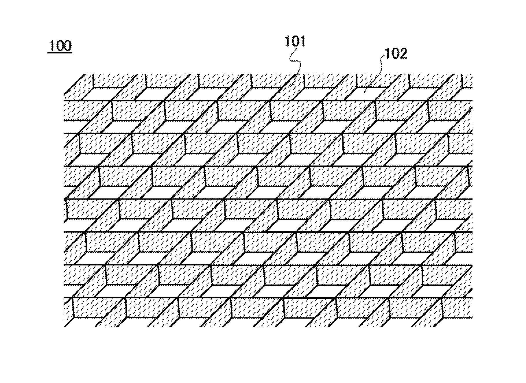
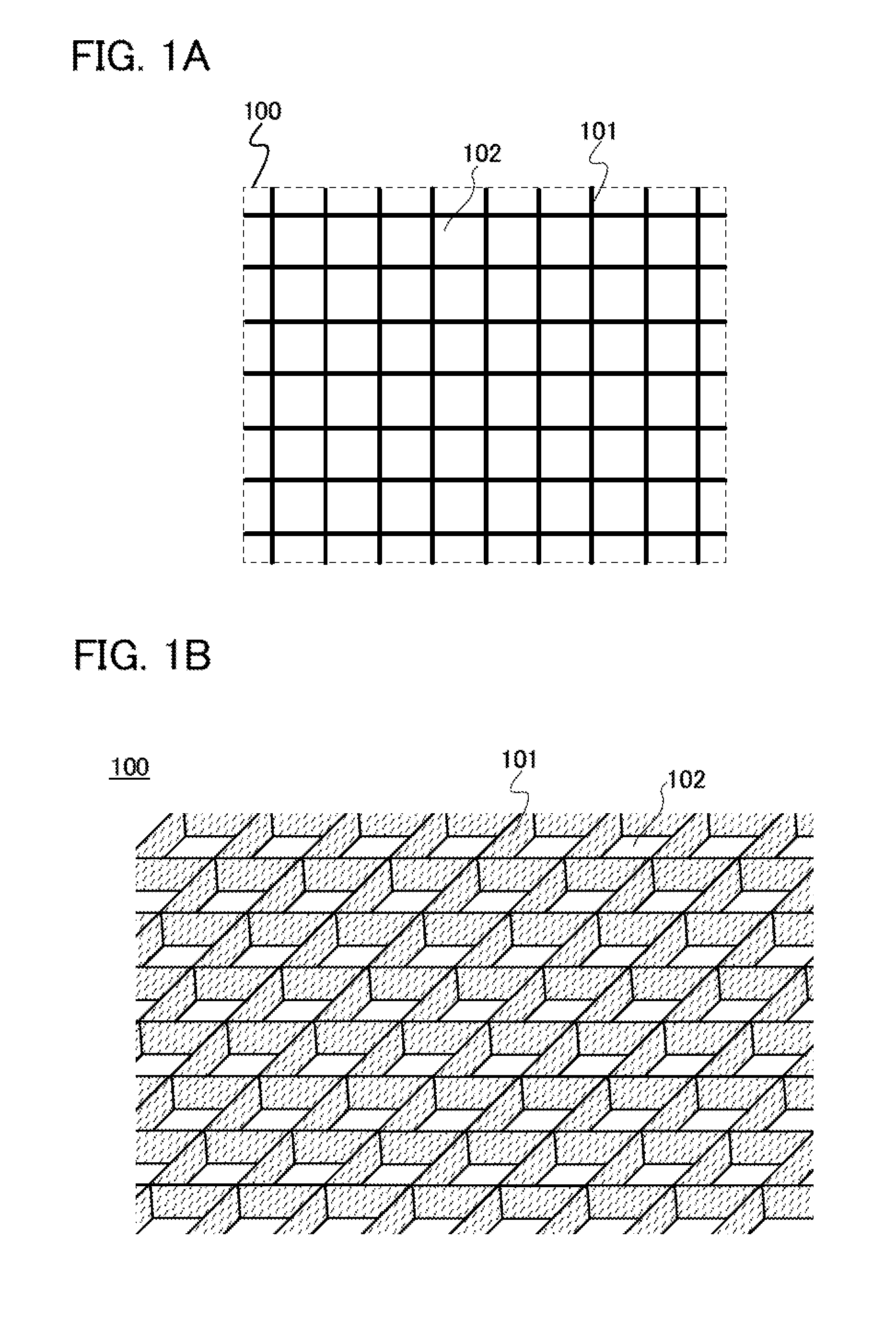
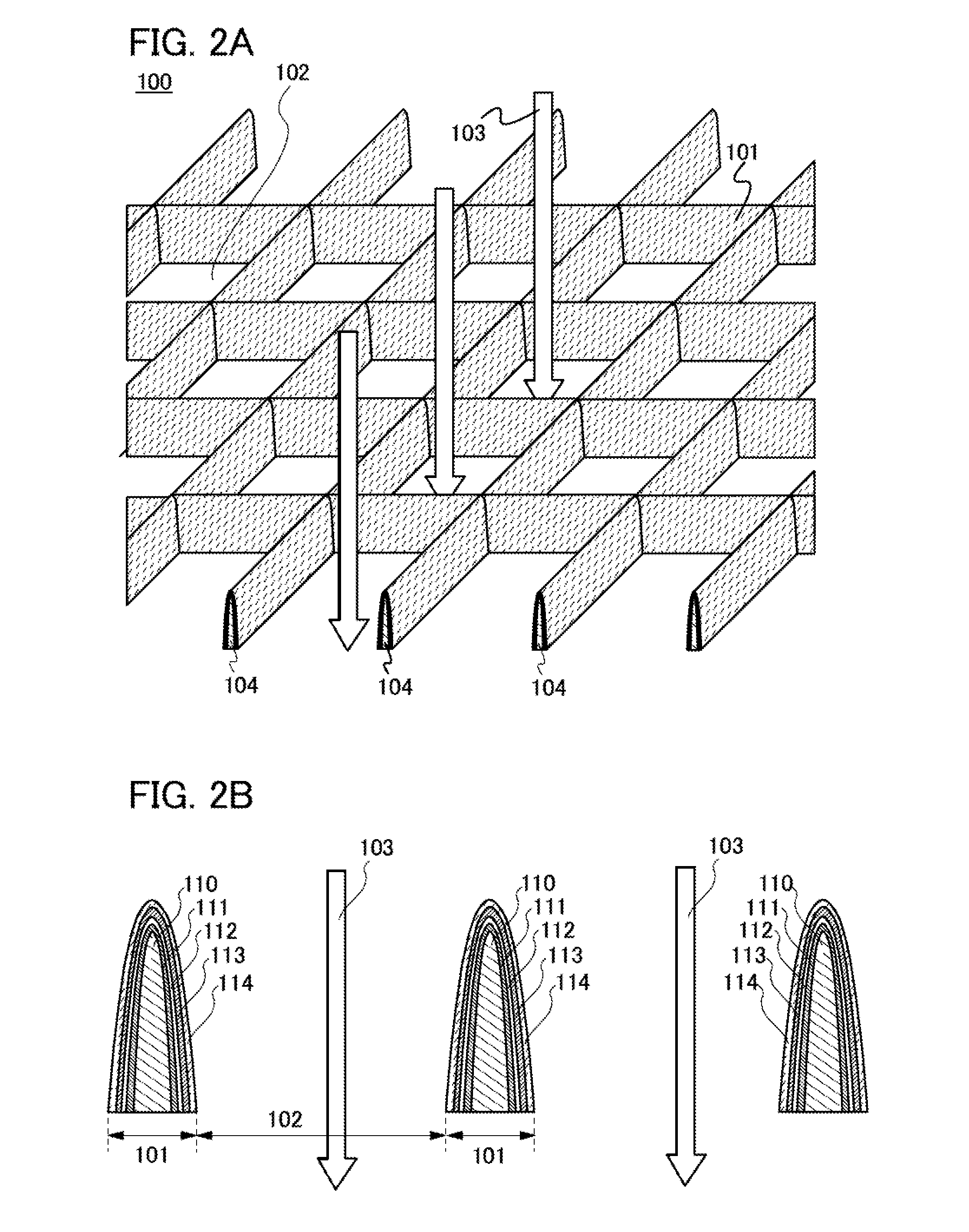
[0038]FIGS. 1A and 1B illustrate a power storage device described in this embodiment. A power storage device 100 is a structure body including at least a positive electrode, a negative electrode, and a solid electrolyte interposed therebetween. FIG. 1A is a plan view of the power storage device 100, and FIG. 1B illustrates a bird's-eye view of the power storage device 100. As illustrated in the plan view in FIG. 1A, the power storage device ...

embodiment 2

[0079]In this embodiment, an example in which a substrate is used for the power storage device described in Embodiment 1 will be described with reference to FIGS. 4A and 4B.

[0080]As illustrated in FIG. 4A which is a perspective view of a power storage device 200, in the power storage device 200 according to this embodiment, a substrate 205 is provided below the power storage device 100 described in Embodiment 1. In other words, thin line portions 201 are formed over the substrate 205. The substrate 205 is formed using a member having a light-transmitting property. Therefore, external light 203 entering from an upper side of the thin line portions 201 passes through openings 202 and is transmitted through the substrate 205 to be extracted outside the power storage device 200. In contrast, external light (not shown) entering from a lower side of the power storage device 200 is transmitted through the substrate 205 and passes through the openings 202 to be extracted toward the upper si...

embodiment 3

[0090]In this embodiment, an example in which an insulating layer is provided such that the openings of the power storage device described in Embodiment 2 are filled with the insulating layer will be described with reference to FIGS. 5A and 5B.

[0091]FIG. 5A is a perspective view of a power storage device 300 according to this embodiment. In a manner similar to that in the power storage device described in Embodiment 2, the power storage device 300 includes thin line portions 301 and openings 302 over a substrate 305. In addition to the above structure, an insulating layer 316 is provided over the thin line portions 301 and over the openings 302 such that the openings 302 are filled with the insulating layer 316. The insulating layer 316 is formed using a material having a light-transmitting property. Therefore, external light 303 is transmitted through the insulating layer 316, the openings 302, and the substrate 305, to be extracted to a lower side of the power storage device 300.

[...


PUM


Abstract

Provided is a power storage device having a high discharge capacitance and a light-transmitting property. The power storage device includes a first current collector having a net-like planar shape; a first active material layer over the first current collector; a solid electrolyte layer over the first active material layer; a second active material layer over the solid electrolyte layer; and a second current collector over the second active material layer.

Description

BACKGROUND OF THE INVENTION[0001]1. Field of the Invention[0002]The present invention relates to an object (a product including a machine, a manufacture, and a composition of matter) and a method (a process including a simple method and a production method). In particular, one embodiment of the present invention relates to a power storage device and a manufacturing method thereof.[0003]2. Description of the Related Art[0004]In recent years, power storage devices such as nonaqueous secondary batteries (e.g., lithium secondary batteries), lithium ion capacitors, and air cells have been widely used as power supplies of consumer electric devices such as information terminals typified by mobile phones and smart phones, display devices like liquid crystal televisions, and game machines.[0005]In particular, because of higher energy density than conventional batteries such as nickel-cadmium batteries, lithium secondary batteries are essential for information society these days as rechargeab...

Claims


Application Information

Patent Timeline
IPC IPC(8): H01G9/048H01M4/74
CPCH01G11/04H01G11/08H01G11/28H01G11/70Y02E60/13H01M4/74H01M4/131H01M10/052H01G9/048Y02E60/10Y02P70/50H01M10/36
Inventor KURIKI, KAZUTAKA
Owner SEMICON ENERGY LAB CO LTD
Why Eureka
Try Eureka