
Spatio-Temporal Directional Light Modulator

a directional light modulator and spatial-temporal technology, applied in the direction of optical elements, instruments, manufacturing tools, etc., can solve the problems of reducing the brightness of the achievable display, occupying a portion of the image frame time, and reducing the power efficiency of the display system

Inactive Publication Date: 2013-10-03
OSTENDO TECH INC
View PDF3 Cites 95 Cited by
  • Summary
  • Abstract
  • Description
  • Claims
  • Application Information

AI Technical Summary

Benefits of technology

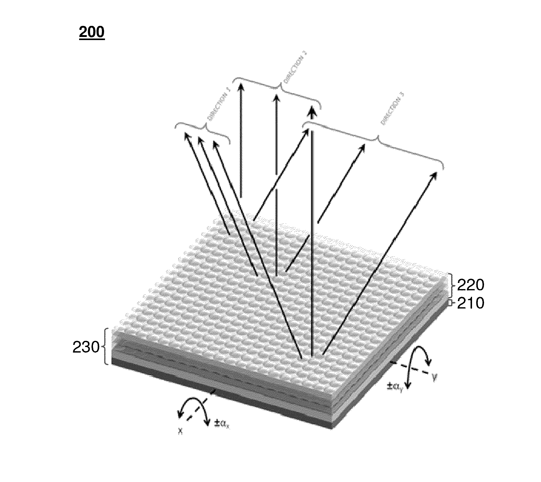
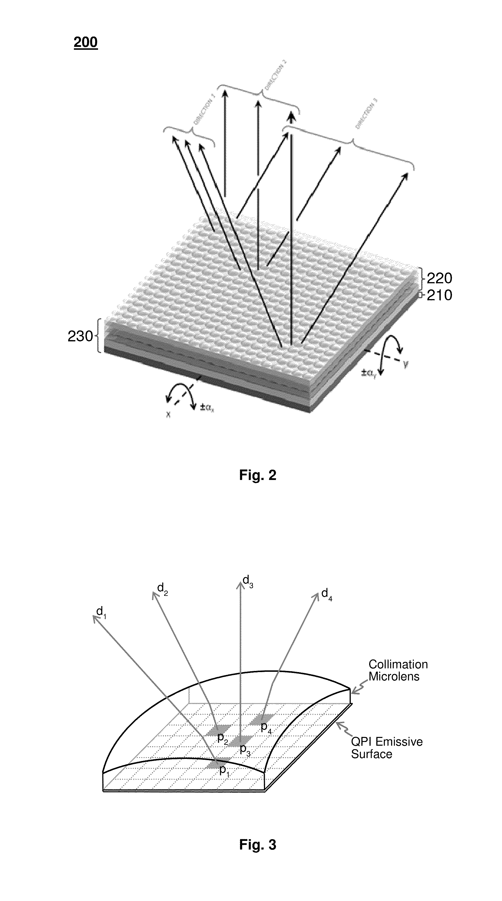
The present invention introduces an improved spatio-temporal light modulator that overcomes the limitations of prior art directional light modulators. The new modulator offers extended angular coverage, allowing for the creation of high resolution 2D and 3D displays with the volumetric advantages of a viewing experience over a wide viewing angle. The new modulator also eliminates the need for narrow spectral bandwidth, high collimation, and individual controllability, reducing the cost and complexity of the overall display system.

Problems solved by technology

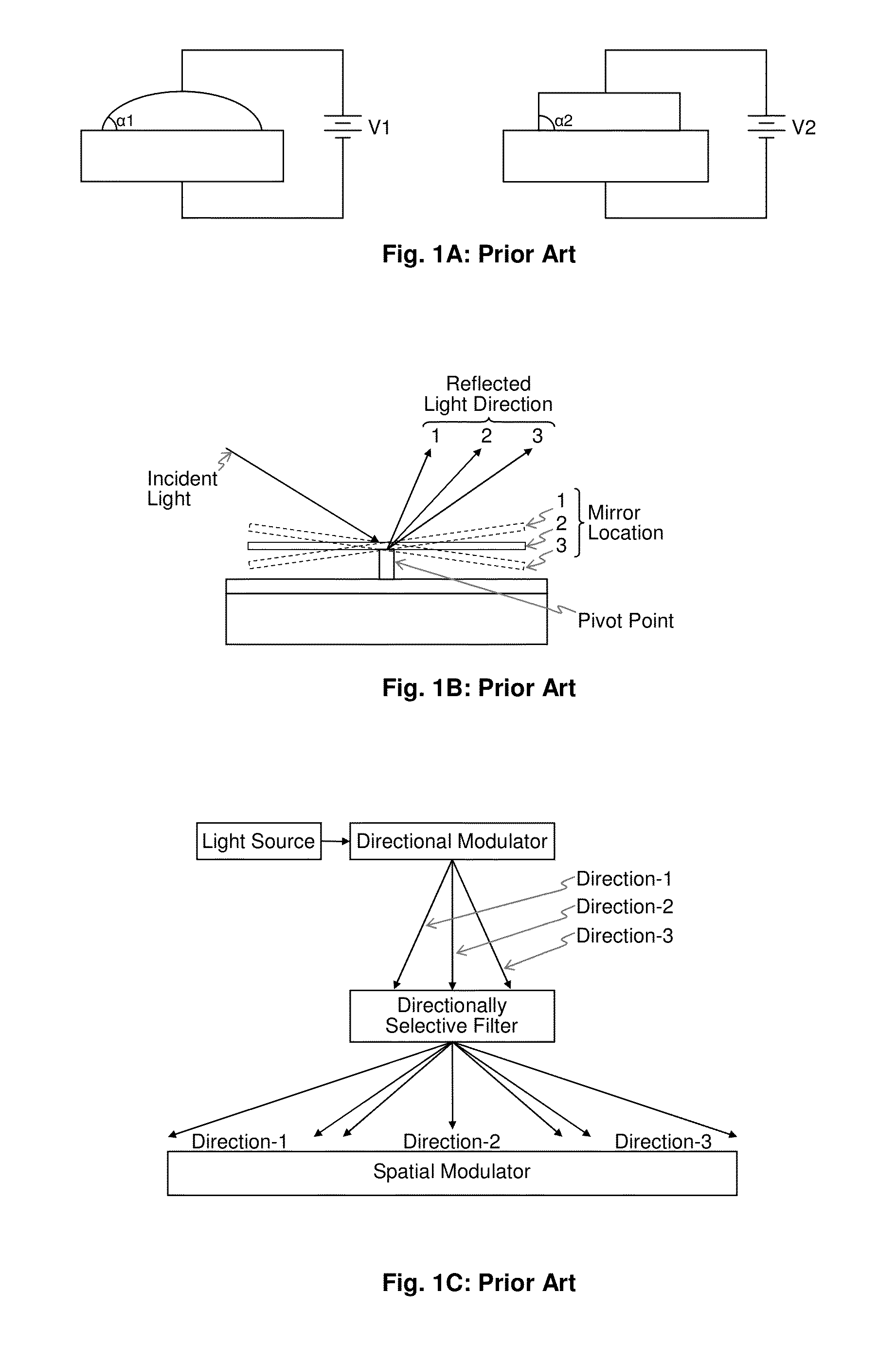
1. Response time: The mechanical movement or optical surface change are typically not achieved instantaneously and affect the modulator response time. In addition, the speed of these operations usually takes up some portion of the image frame time that reduces the achievable display brightness.
2. Volumetric aspects: These methods need a distance between the light source and directional modulation device to work with, which increases the total volume of the display.
3. Light loss: Coupling light on to a moving mirror creates light losses which in turn degrades the display system power efficiency and creates heat that has to be eliminated by incorporating bulky cooling methods that add more volume and increased power consumption.
In addition to being slow, bulky and optically lossy, the prior art directional backlight units need to have narrow spectral bandwidth, high collimation and individual controllability for being combined with a directionally selective filter for 3D display purposes.
Achieving narrow spectral bandwidth and high collimation requires device level innovations and optical light conditioning, increasing the cost and the volumetric aspects of the overall display system.
Achieving individual controllability requires additional circuitry and multiple light sources increasing the system complexity, bulk and cost.
U.S. patent application Ser. No. 13 / 329,107 introduced a novel spatio-optical directional light modulator that overcomes most all of these drawbacks, however its angular coverage is limited by the numerical aperture of its light collimation optics.

Method used


Image

  • Spatio-Temporal Directional Light Modulator
  • Spatio-Temporal Directional Light Modulator
  • Spatio-Temporal Directional Light Modulator

Examples


embodiment 600

[0049]Referring to the side view illustration of FIG. 6, the articulation of the hinged interior segment 625 together with the bonded QPI / MLA assembly 230 would be accomplished using a set of electromagnets 635 placed at the four corners of the backside of the hinged interior segment 625, and a set of permanent magnets 636 placed on the topside of base layer 630 in alignment with the four corners of the backside of the hinged interior segment 625. The electromagnets 635 would be a coil having a metal core formed at wafer level using multilayer imprint lithography on the backside of the hinged interior segment 625. The permanent magnets 636 would be a thin magnetic strip typically of neodymium magnet (Nd2Fe14B) or the like. Articulation of the hinged interior segment 625 together with the bonded QPI / MLA assembly 230 as described earlier would be accomplished by driving the set of electromagnets 635 with an electrical signal having the appropriate temporal amplitude variation to affec...

embodiment 700

[0052]The hinged pad 721 / 735 is retained in place within the surface curvature of the pedestal 730 / 736 by the spring layer 725 which contains at each of its four corners a single spiral shaped spring 726 that is etched into the spring layer 725. As illustrated in FIG. 7 exploded view isometric, the inner end of each of the four spiral shaped springs incorporates an inner bonding pad 727 which corresponds to an identical bonding pad 722 located at the backside of the pad layer 721. Embedded within the spiral shaped springs 726 are multiple metal rails that are used to route the electrical interface signals from its inner bonding pad 727 to a set of contact pads 728 located at the peripheral edge of the backside of the spring layer 725. The edge contacts 728 on the backside of the outer end of the spring layer 725 correspond to a matching set of bonding pads 729 that are located at the peripheral edge of the base layer 730. The edge contacts on the topside of the base layer 730 are co...


PUM

PropertyMeasurementUnit
Lengthaaaaaaaaaa
Timeaaaaaaaaaa
Coloraaaaaaaaaa

Abstract

A spatio-temporal directional light modulator is introduced. This directional light modulator can be used to create 3D displays, ultra-high resolution 2D displays or 2D / 3D switchable displays with extended viewing angle. The spatio-temporal aspects of this novel light modulator allow it to modulate the intensity, color and direction of the light it emits within an wide viewing angle. The inherently fast modulation and wide angular coverage capabilities of this directional light modulator increase the achievable viewing angle, and directional resolution making the 3D images created by the display be more realistic or alternatively the 2D images created by the display having ultra high resolution.

Description

CROSS-REFERENCE TO RELATED APPLICATIONS[0001]This application claims the benefit of U.S. Provisional Patent Application No. 61 / 616,249 filed Mar. 27, 2012.BACKGROUND OF THE INVENTION[0002]1. Field of the Invention[0003]The present invention relates to the field of directional light modulation, 3D displays, emissive micro displays, 2D / 3D switchable displays.[0004]2. Prior Art[0005]In 3D displays, directional modulation of the emitted light is necessary to create the 3D viewing perception. In a typical 3D display, a backlight with uniform illumination in multiple illumination directions is required to display images of the same scene from different directions by utilizing some combination of spatial multiplexing and temporal multiplexing in the spatial light modulator. In these 3D displays the light that typically comes from the directional backlight is usually processed by a directionally selective filter (such as diffractive plate or a holographic optical plate for example) before i...

Claims


Application Information

Patent Timeline
IPC IPC(8): G02B26/08G02B7/00H04N13/307
CPCG02B26/101H04N13/0406Y10T29/4978H04N13/0452G02B26/08H04N13/0418Y10T29/49826H04N13/32H04N13/356H04N13/307
Inventor EL-GHOROURY, HUSSEIN S.ALPASLAN, ZAHIR Y.CAI, JINGBOMAIERS, MARTYWARNER, PHILIPMCNEILL, DALE A.
Owner OSTENDO TECH INC
Learn More