

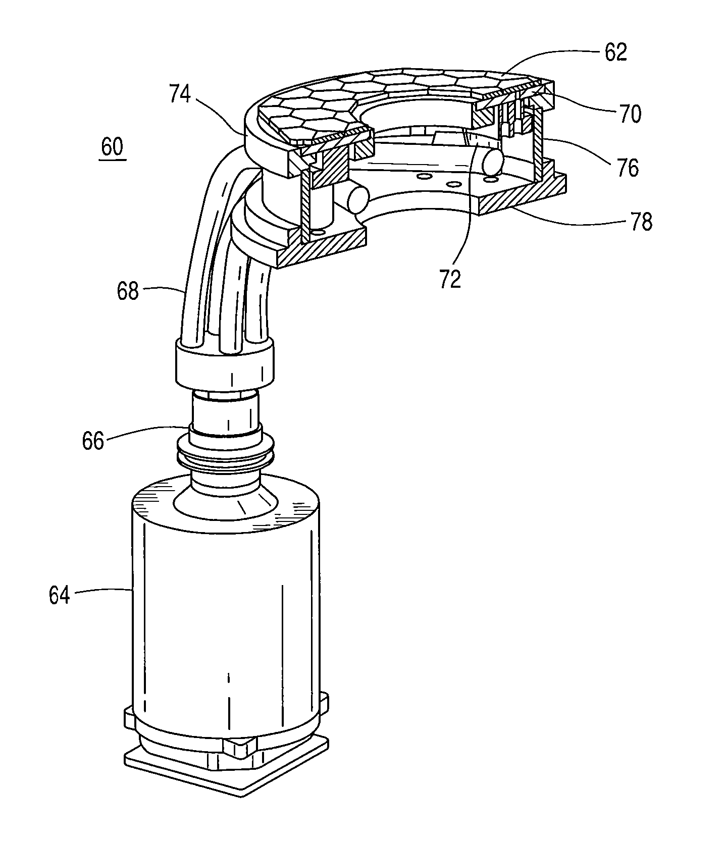
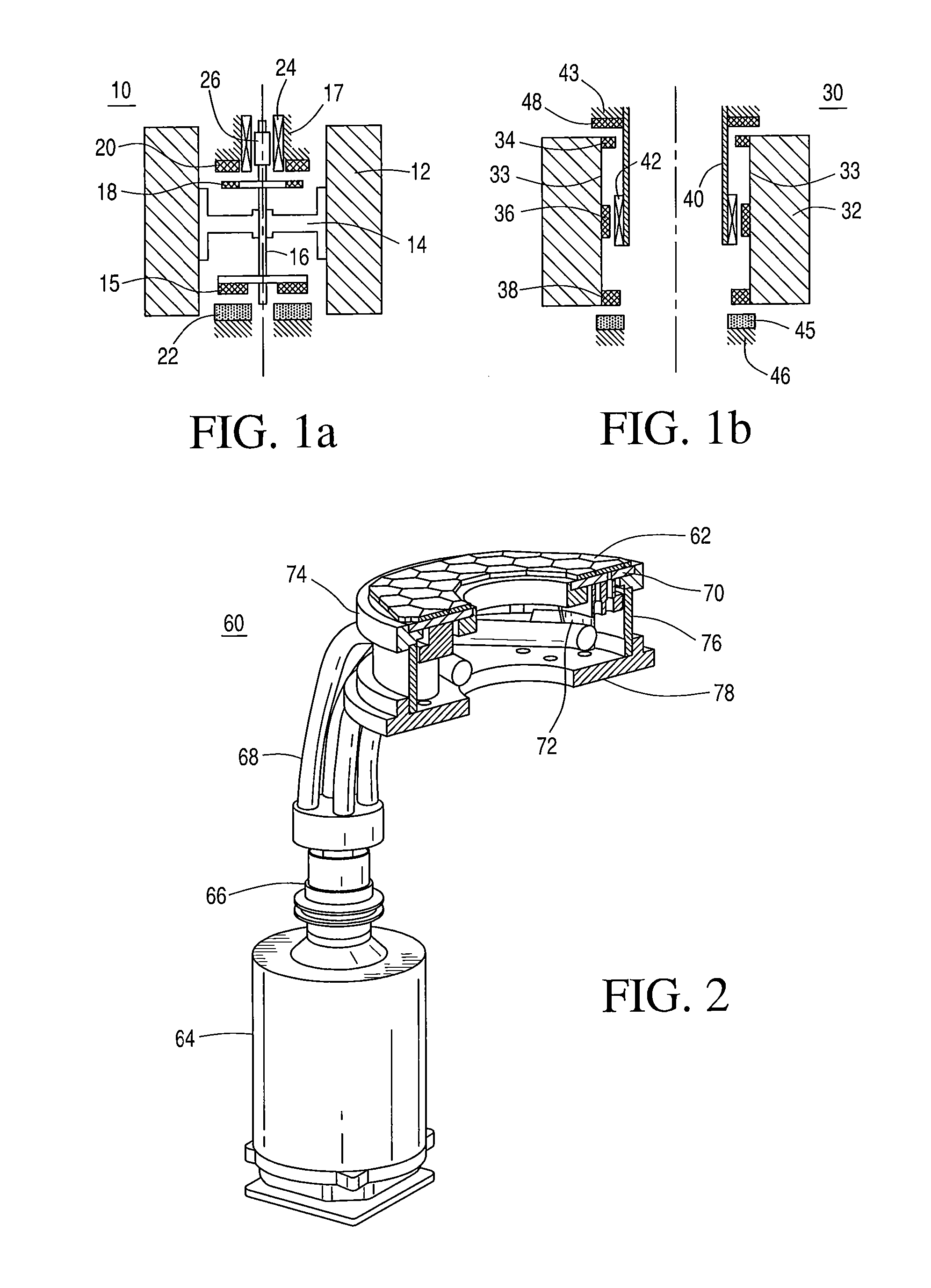
Open-core flywheel architecture
a flywheel and core technology, applied in the direction of superconducting magnets/coils, magnetic bodies, superconductor devices, etc., can solve the problems of flywheel performance, the design of the shaft and the hub is limited in terms of its achievable upper-end velocity, and the difficulty in matching the useable materials of components in the flywheel assembly
- Summary
- Abstract
- Description
- Claims
- Application Information
AI Technical Summary
Benefits of technology
Problems solved by technology
Method used
Image

Examples
Embodiment Construction
[0021]According to the present disclosure, there are several key technologies that are incorporated into the open-core flywheel architecture to achieve the desired high energy density in the flywheel energy storage devices to obtain superior results and performance. Such advances include incorporating rotors made from high-strength materials, and incorporating a rotor in an open-core (hubless) flywheel architecture with a high-temperature superconductive (HTS) bearing technology.
[0022]Carbon nanotubes (CNTs) are allotropes of carbon with a cylindrical nanostructure. Nanotubes have been constructed with length-to-diameter ratio of up to 132,000,000:1, significantly larger than for any other material. These cylindrical carbon molecules have unusual properties that are valuable for nanotechnology, electronics, optics and other fields of material science and technology. Because of their thermal conductivity and mechanical and electrical properties, carbon nanotubes find applications as ...
PUM
 Abstract
Description
Claims
Application Information