Nested-rotor open-core flywheel

Active Publication Date: 2013-10-03
THE BOEING CO
View PDF11 Cites 22 Cited by
  • Summary
  • Abstract
  • Description
  • Claims
  • Application Information

AI Technical Summary

Benefits of technology

[0005]The present disclosure is directed to a flywheel and flywheel architecture that eliminates the material growth-matching problem and obviates radial growth and bending mode issues that otherwise occur

Problems solved by technology

The shaft-and-hub flywheel design is limited in terms of its achievable upper-end velocity.
Matching useable materials for components in the flywheel assembly has been problematic since the radial growth of the components varies as the rotor velocity increases.
Therefore, the higher speeds for flywheels enabled by the use of ever-advancing materials unfortunately exacerbates the growth-matching problem for the hub as the increased radial growth of the rim outpaces any growth exhibited by other connected components such as, for example, the connecting shaft.
Further, the overall

Method used


Image

  • Nested-rotor open-core flywheel
  • Nested-rotor open-core flywheel
  • Nested-rotor open-core flywheel

Examples


Embodiment Construction

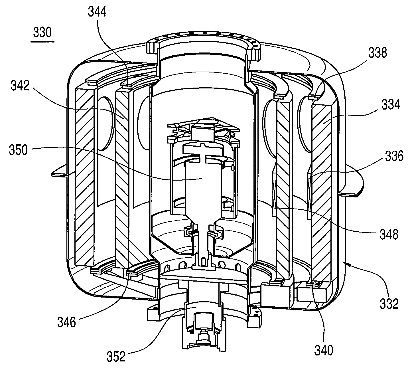
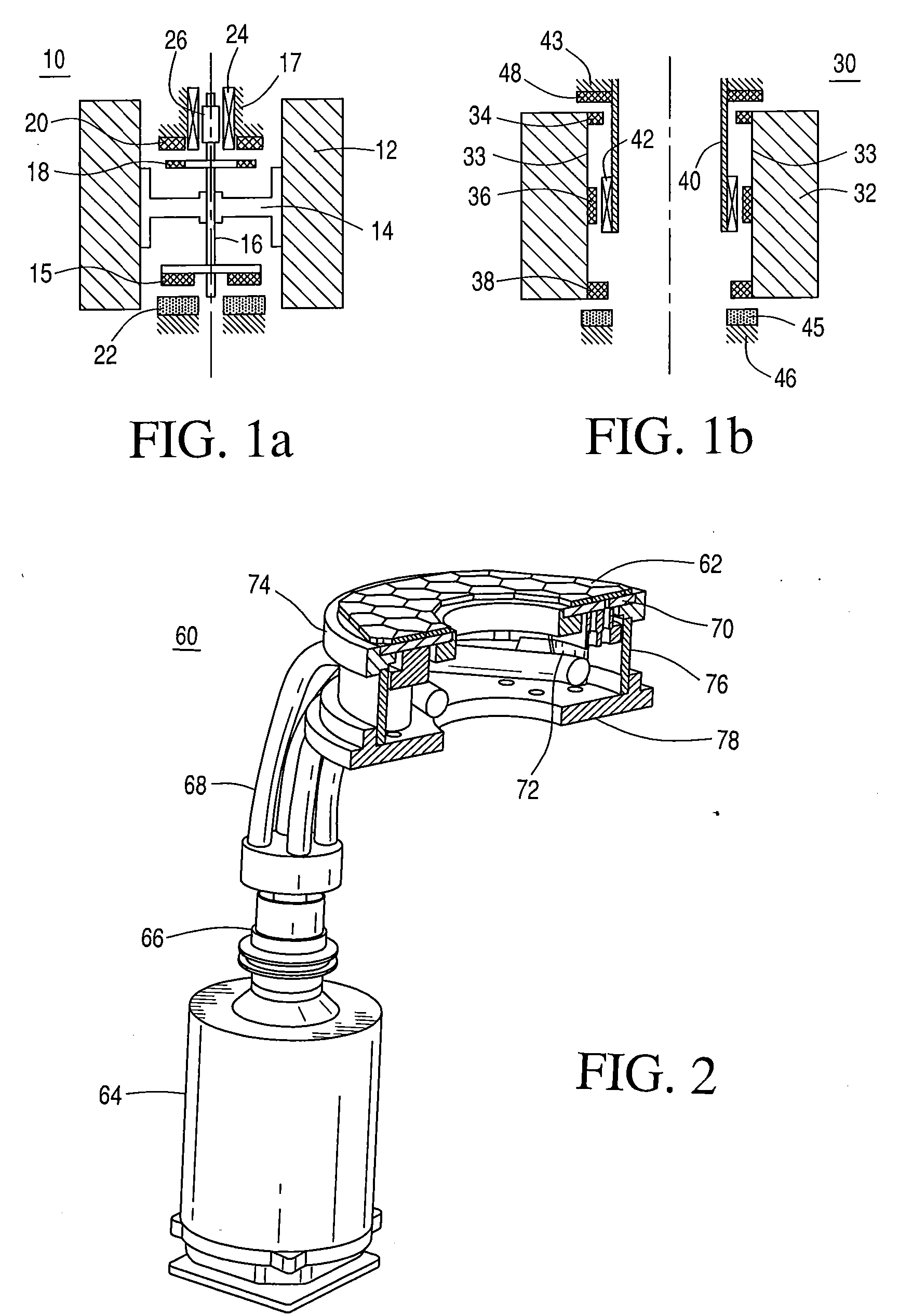
[0029]According to the present disclosure there are several key technologies that are incorporated into the open-core flywheel architecture to achieve the desired high energy density in the flywheel energy storage devices to obtain superior results and performance. Such advances include incorporating rotors made from high-strength materials, and incorporating a plurality of rotors in an open-core flywheel architecture with a high-temperature superconductive (HTS) bearing technology.

[0030]According to the present disclosure, the rotors preferably comprise high-strength materials such as, for example, carbon fiber-containing, glass fiber-containing, metal-containing materials and combinations thereof, etc. Carbon nanotubes (CNTs)-containing materials are particularly preferred. Such materials are allotropes of carbon with a cylindrical nanostructure. Nanotubes have been constructed with length-to-diameter ratio of up to 132,000,000:1, significantly larger than for any other material. ...


PUM


Abstract

Methods and apparatuses are disclosed for incorporating a plurality of independently rotating rotors made from high-strength materials with a high-temperature superconductive (HTS) bearing technology into an open-core flywheel architecture to achieve a desired high energy density in the flywheel energy storage devices and to obtain superior results and performance.

Description

[0001]The present disclosure relates to flywheel energy storage devices and, more particularly, to hubless, or open-core flywheel storage devices having improved stability and performance.BACKGROUND[0002]Flywheel energy storage devices and systems are known for storing energy and releasing stored energy on demand. Known flywheel assemblies have a traditional rotor design sometimes made with carbon fiber composites. Such rotors have a shaft on which the motor / generator (M / G) and bearing permanent magnets (PMs) are mounted. The shaft is conventionally connected to the rim via a hub. The shaft-and-hub flywheel design is limited in terms of its achievable upper-end velocity. Matching useable materials for components in the flywheel assembly has been problematic since the radial growth of the components varies as the rotor velocity increases. The hub must mechanically couple the shaft to the rim without introducing bending modes into the rotor structure through the range of operating fre...

Claims


Application Information

Patent Timeline
IPC IPC(8): H02K7/02H01L39/02B82Y99/00H02K7/18
CPCH02K7/025H02K7/09Y10T74/212Y02E60/16Y10T74/2119H02K16/00F16C32/0438F16C2361/55
Inventor HULL, JOHN R.STRASIK, MICHAELMITTLEIDER, JOHN A.WILENSKI, MARK S.KOZAR, MICHAEL P.
Owner THE BOEING CO
Why Eureka
Try Eureka