Device and method for processing target component in tube

Active Publication Date: 2013-10-17
SHIMADZU CORP
View PDF1 Cites 69 Cited by
  • Summary
  • Abstract
  • Description
  • Claims
  • Application Information

AI Technical Summary

Benefits of technology

[0046]According to the present invention, it is possible to provide a small and low running-cost device capable of minimizing the generation of contamination sources as much as possible while performing a series of all the desired manipulations.
[0047]According to the present invention, it is po

Problems solved by technology

Commercially-available systems that perform a series of processes from extraction of nucleic acid from cells to analysis by gene amplification reaction in a single device can simultaneously treat only a small number of samples, and are not suitable for practical use because the device itself is complicated and its production cost is high.
For example, in the case of GeneXpert

Method used


Image

  • Device and method for processing target component in tube
  • Device and method for processing target component in tube
  • Device and method for processing target component in tube

Examples


Example

Example 1

Extraction / Purification of Nucleic Acid from Blood

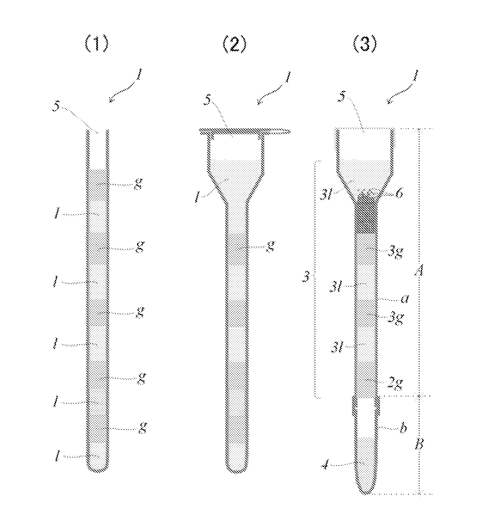
[0225]A gelating agent (TAISET 26 manufactured by Taiyo Kagaku Co., Ltd.) was added to silicone oil (KF-56 manufactured by Shin-Etsu Silicone) at 1.2% (weight ratio) and heated to 70° C. to be completely mixed with the silicone oil. The required amounts of the oil put into a sol state by mixing and a necessary reagent were alternately injected into a manipulation tube shown in FIG. 3(0) (constituted from a capillary (manipulation part A) and a sample tube (recovery part B)) through the tip of a syringe needle without trapping air bubbles to form multiple layers. When the capillary had an inner diameter of 1.5 mm, as shown in FIG. 3(0), each gel plug was formed by charging 10 μL of the oil, each washing liquid layer was formed by charging 15 μL of a washing liquid (200 mM KCl), and an eluent layer was formed by charging 20 μL of an eluent (10 mM Tris HCl, 1 mM EDTA pH 8.0). After the charging was completed, the capillary was ...

Example

Example 2

Detection of Influenza Virus from Nasal Cavity Swab

[0230]A manipulation tube (capillary device) shown in FIG. 4(0) was filled with reagents and a gel in the same manner as in Example 1 except that a reverse transcription reaction liquid (RT reaction liquid) and a PCR reaction liquid were further used. The capillary device used in this example was not the capillary device used in Example 1 in which a recovery sample tube was attached to the lower end of a capillary but a capillary device integrally formed to have a blind lower end. By covering a sample supply port of this capillary device with a septum, a completely hermetically sealed PCR device with nucleic acid extraction function is obtained. Detection was performed by fluorescence detection using a fluorescent dye such as SYBR Green I based on a real-time detection method or an end-point detection method.

[0231]During nucleic acid extraction in the capillary device shown in FIG. 4, sample addition and magnet manipulation...


PUM

PropertyMeasurementUnit
Diameteraaaaaaaaaa
Diameteraaaaaaaaaa
Temperatureaaaaaaaaaa

Abstract

The present invention provides a small and low running-cost device capable of minimizing the generation of contamination sources as much as possible while performing a series of all the desired manipulations. A device for manipulating a target component in a manipulation tube, comprising: a manipulation tube comprising a tube having an optionally-closeable open end for supplying a sample containing a target component at one end and a closed end at the other end, and a manipulation medium accommodated in the tube and having a gel layer and an aqueous liquid layer multilayered in a longitudinal direction of the tube; magnetic particles that should transport the target component; and magnetic field applying means capable of applying a magnetic field to the manipulation tube to move the magnetic particles in the longitudinal direction of the tube.

Description

TECHNICAL FIELD[0001]The present invention relates to a device and a method for manipulating a target component with the use of a gel. More specifically, the present invention relates to a device and a method capable of subjecting a target component to various manipulations in a hermetically-sealable tube by manipulating magnetic particles in the tube with a magnetic field from the outside of the tube. Even more specifically, the present invention relates to a device and a method capable of performing extraction, purification, synthesis, elution, separation, recovery, and analysis of a target component by manipulating magnetic particles in a tubule in which a reagent liquid is accommodated with the use of an oil gel.BACKGROUND ART[0002]Water-insoluble microparticles having a diameter of a dozen or so micrometers to 0.5 μm can be used to extract / purify, separate, and recover a target component by allowing the surface of the microparticles to have various chemical affinities. Further,...

Claims


Application Information

Patent Timeline
IPC IPC(8): B03C1/00
CPCB03C1/00B01L3/5025B01L3/5082B01L2200/0647B01L2200/0673B01L2300/0832B01L2300/0861B01L2300/087B01L2400/043B01J2219/00364B01J2219/00466B01J2219/00468B03C1/01B03C1/0332B03C1/288B03C1/30B03C2201/18B03C2201/26G01N35/0098Y10T29/49826B03C1/12
Inventor OHASHI, TETSUO
Owner SHIMADZU CORP
Why Eureka
Try Eureka