Eureka AIR delivers breakthrough ideas for toughest innovation challenges, trusted by R&D personnel around the world.

Circulating fluidized bed boiler

a fluidized bed and boiler technology, applied in the direction of fluidised bed combustion apparatus, combustion types, lighting and heating apparatus, etc., can solve the problems of insufficient penetration of secondary air in the furnace, affecting the flow field, and affecting so as to improve the performance of combustion and discharge, the effect of effectively absorbing and improving the temperature of the bed

Active Publication Date: 2013-10-31
INST OF ENGINEERING THERMOPHYSICS - CHINESE ACAD OF SCI
View PDF9 Cites 3 Cited by
  • Summary
  • Abstract
  • Description
  • Claims
  • Application Information

AI Technical Summary

Benefits of technology

The present invention is a circulating fluidized bed boiler that improves secondary air penetration and increases the area of the water wall in the furnace. This is achieved by using water cooling tubes that form at least one vertical columnar recessed segment towards the inside of the furnace. The technical effects of this invention include: (1) improved combustion and discharge performance by allowing secondary air to easily reach the center region of the furnace; and (2) better control of the bed temperature and flue gas temperature at the furnace outlet by arranging more heating surface in the furnace.

Problems solved by technology

The oxygen can be transversely moved, in the region beyond the penetration distance of the secondary air, only by a transverse mixing of materials, which is rather difficult.
Accordingly, the insufficient penetration of the secondary air in the furnace is a great challenge for large-size circulating fluidized bed boiler.
However, there is higher requirement for the design of the water-cooling column, and the improper design will affect the flow field of the furnace and the inlet of cyclone.
Furthermore, since the water-cooling column is located in the furnace, it is inconvenient for the maintenance.
Furthermore, with the scaling-up and high-parameter of circulating fluidized bed boiler, a ratio of the dimension to surface area of the furnace increases, which makes it difficult to match the combustion and heat transfer in the furnace.
However, such solution will bring some difficulty in the seal, inflation and anti-abrasion of the furnace, and cause uneven heat absorbance of the upper part of the furnace and make the temperature of the upper part of the furnace and the flue gas temperature at the furnace outlet relatively lower.
However, the external heat exchanger increases the cost of manufacture, operation and maintenance of the whole boiler system, and meanwhile it puts forwards a strict request on the overall arrangement and operation adjustment of the circulating fluidized bed boiler.

Method used


Image

  • Circulating fluidized bed boiler
  • Circulating fluidized bed boiler
  • Circulating fluidized bed boiler

Examples


embodiment 1

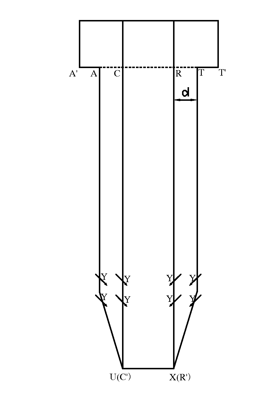
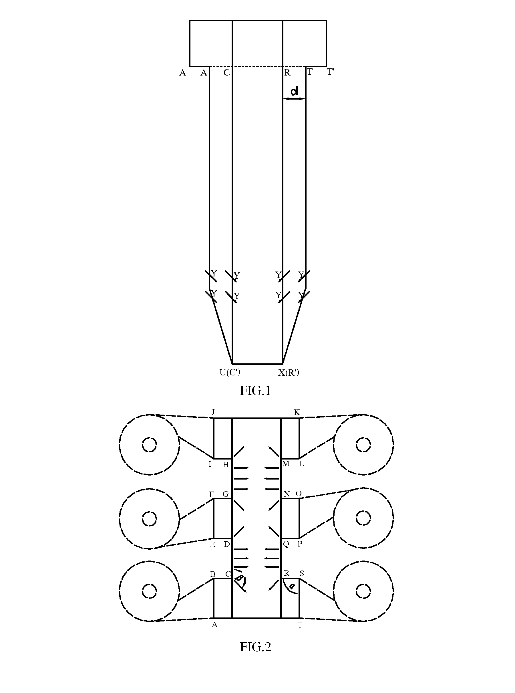
[0047]The circulating fluidized bed boiler shown in FIGS. 1-2 comprises six cyclones arranged outside left and right side walls, respectively. There are two vertical columnar recessed segments extending from air distributor to the furnace ceiling in the left and right side walls, respectively, so that the cross section of furnace exhibits a polygon ABCDEFGHIJKLMNOPQRST. The side walls and the columnar recessed segments are all constructed by vertical water walls. Three furnace flue gas outlets AB, EF and IJ are provided in the upper part of the left side wall AJ, and two columnar recessed segments are provided between the furnace flue gas outlets and exhibit rectangle notches BCDE and FGHI in the view of furnace cross section. The notch width (that is, the columnar recessed segment width) is equal to the net distance between the furnace flue gas outlets, that is, CD=BE, GH=FI. The right side wall TK has two rectangle notches SRQP and ONML, which are designed the same as those of the...

embodiment 2

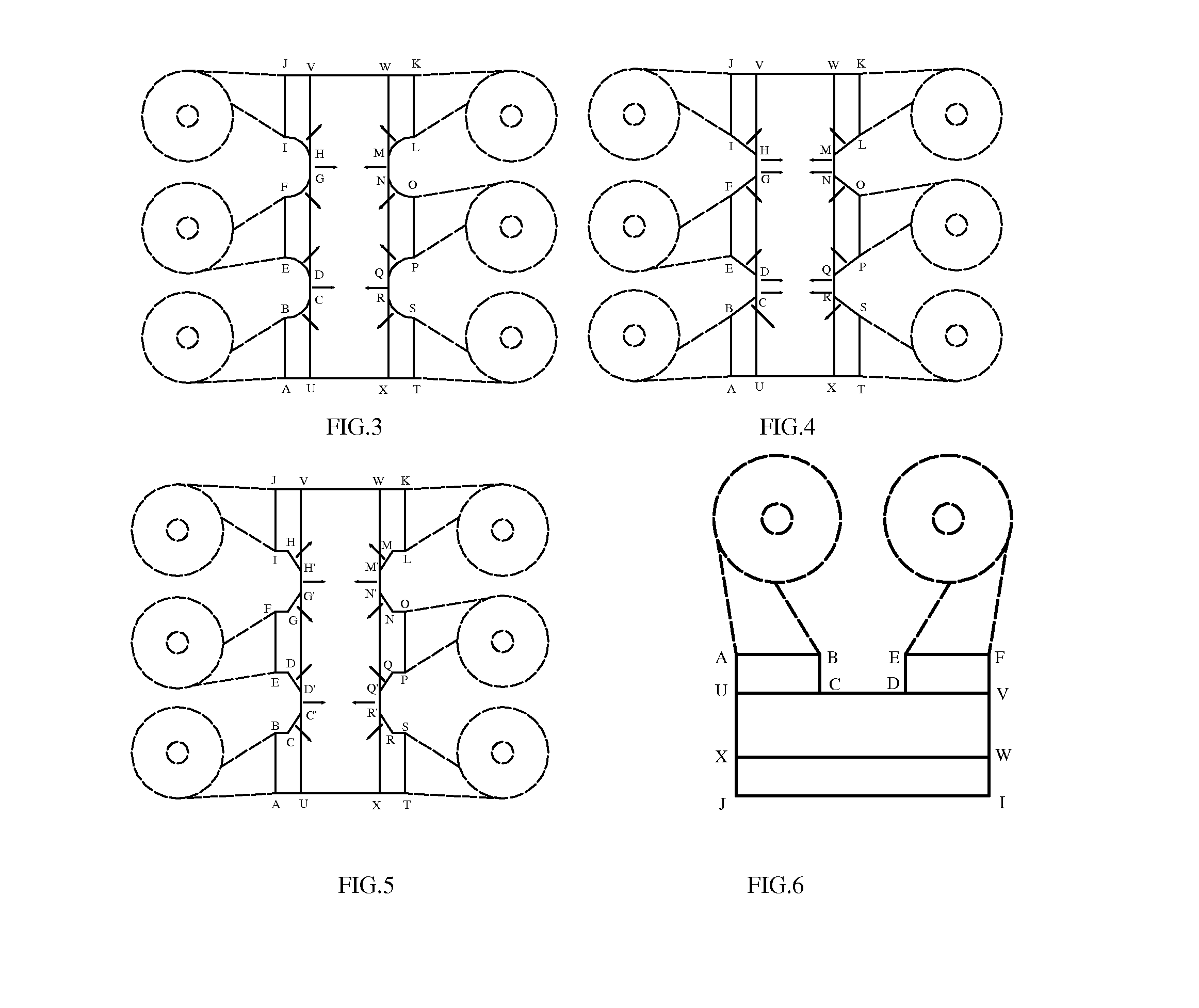
[0051]In the circulating fluidized bed boiler shown in FIGS. 6-7, two furnace flue gas outlets AB, EF are provided in the upper part of the rear wall and connected with two cyclones, respectively. Solid outlets of the cyclones are connected with a loop-seal (not shown), the loop-seal is connected with the lower part of the furnace, the flue gas outlet of the cyclone is connected with flue gas duct (not shown).

[0052]There is one vertical columnar recessed segment BCDE in the furnace rear wall AF, so that the cross section of the furnace exhibits a rectangle with a rectangle notch, which is located between two furnace flue gas outlets AB and EF. The width of the notch is equal to the net distance between the two furnace flue gas outlets, and the depth is equal to a half of the difference between the width AT of the upper part of the furnace and the width UX of air distributor, and the height is equal to the height of the furnace (that is, the columnar recessed segment extends from the...

embodiment 3

[0058]In the circulating fluidized bed boiler shown in FIGS. 15-16, each of the left and right side walls of the furnace is provided with two flue gas outlets, and these four furnace flue gas outlets are connected with four cyclones respectively. Each of the left and right side walls is provided with a vertical columnar recessed segment. Therefore, the cross section of the furnace at the furnace flue gas outlet exhibits a rectangle with two symmetrical rectangular notches, that is, ‘I’-shape. The notches are located respectively between two furnace flue gas outlets at the same side wall. The width of the notch is equal to the net distance between the two furnace flue gas outlets, the depth is less than a half of the difference between the depth of the upper part of the furnace and the depth of the air distributor, and the height is equal to 90% of the furnace height. The columnar recessed segment extends from a position above the air distributor and below the lower layer of secondar...


PUM


Abstract

A circulating fluidized bed boiler is disclosed. The circulating fluidized bed boiler comprising: a furnace defined and enclosed by water walls, a ceiling and an air distributor, the water walls comprising front and rear walls and left and right side walls (AJ, TK) formed by water cooling tubes, and the water walls are provided with secondary air ports (Y) in the lower part thereof, and furnace flue gas outlets (AB, EF, IJ, KL, OP, ST) being provided in an upper part of the furnace; at least two cyclones connected with the furnace flue gas outlets (AB, EF, IJ, KL, OP, ST); a loop-seal is connected with solid outlets of the cyclones and the lower part of the furnace, respectively; and a flue gas duct connected with flue gas outlets of the cyclones wherein the water cooling wall tubes of the water wall form at least one vertical columnar recessed segment (BCDE, FGHI, SRQP, ONML) recessed toward the inside of the furnace, and the at least one columnar recessed segment (BCDE, FGHI, SRQP, ONML) extends at least 15% of the furnace height in a vertical direction.

Description

FIELD OF THE INVENTION[0001]The present invention relates to a large-size circulating fluidized bed boiler, in particular to the furnace of a circulating fluidized bed boiler.DESCRIPTION OF THE RELATED ART[0002]With the scaling up of a circulating fluidized bed boiler, the area of furnace cross section and air distributor should be larger correspondingly. Thereby, the distance between a secondary air outlet in a side wall of the furnace and the center region of the furnace becomes longer. Furthermore, the increase in the density of particles in furnace leads to greater resistance for the secondary air transversely penetrating to the center region of the furnace. The oxygen can be transversely moved, in the region beyond the penetration distance of the secondary air, only by a transverse mixing of materials, which is rather difficult. Accordingly, the insufficient penetration of the secondary air in the furnace is a great challenge for large-size circulating fluidized bed boiler.[000...

Claims


Application Information

Patent Timeline
IPC IPC(8): F22B31/00F23C10/18
CPCF22B31/003F23C10/18F22B31/0084F23C10/10F22B21/02F22B31/00F23M5/08
Inventor LV, QINGGANGSUN, YUNKAISONG, GUOLIANGWANG, DONGYUBAO, SHAOLINGAO, MINGLI, SHIYUAN
Owner INST OF ENGINEERING THERMOPHYSICS - CHINESE ACAD OF SCI
Why Eureka
Eureka Blog
Learn More