

Ultrasound image capture device, ultrasound image capture method, ultrasound image capture program
- Summary
- Abstract
- Description
- Claims
- Application Information
AI Technical Summary
Benefits of technology
Problems solved by technology
Method used
Image

Examples
embodiment 1
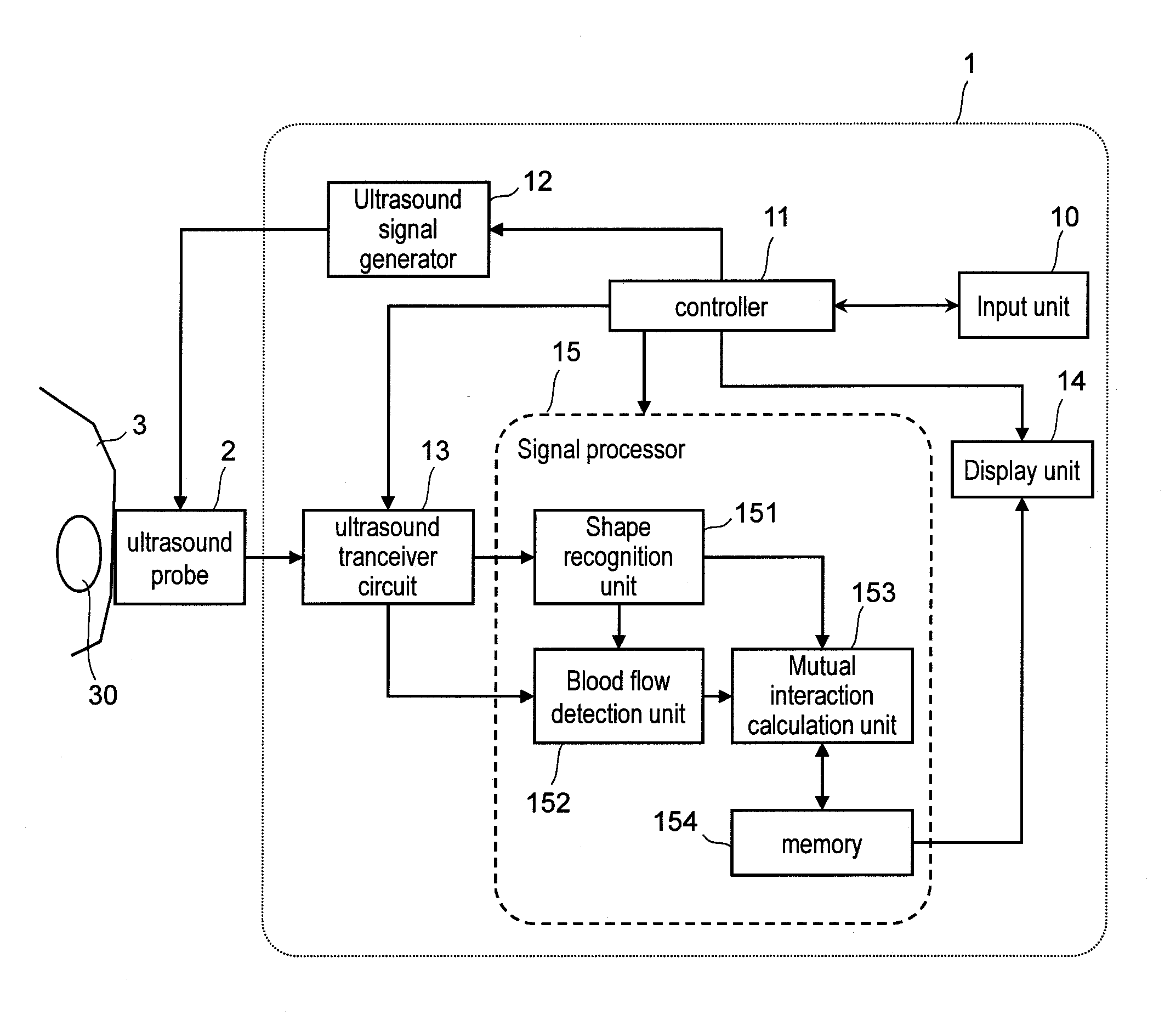
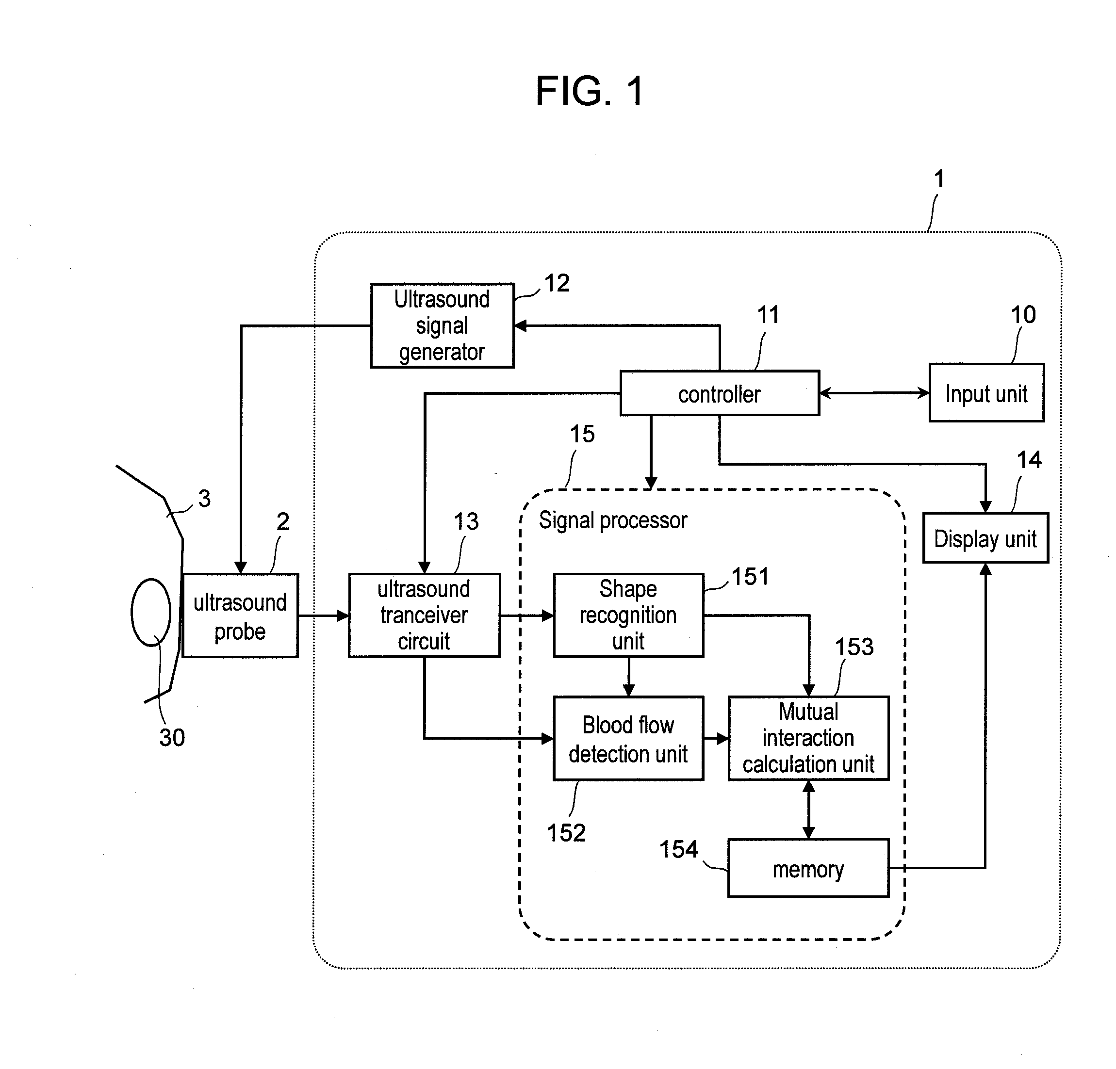
[0026]FIG. 1 is a functional block diagram of an ultrasound imaging device according to the present invention. The ultrasound imaging device 1 is a device that irradiates an ultrasound wave from an ultrasound probe 2 to a subject 3 (e.g. biological body), receives a reflected echo signal, and generates an ultrasound image of the subject. The ultrasound probe 2 irradiates an ultrasound wave to an irradiation region 30 of the subject 3 according to a signal generated by an ultrasound signal generator 12, and receives a reflected echo signal of the irradiation region 30.
[0027]The ultrasound imaging device 1 includes an input unit 10, a controller 11, the ultrasound signal generator 12, an ultrasound receiver circuit 13, a display unit 14, and a signal processor 15. “ultrasound transceiver” in the present invention corresponds to the controller 11, the ultrasound signal generator 12, and the ultrasound receiver circuit 13.
[0028]The input unit 10 is an operation device for operators who ...
embodiment 2
[0100]As described thus far, the ultrasound imaging device 1 approximates the blood vessel as a cylinder, and estimates the blood flow velocity vectors in the blood vessel using fluid analytical methods in cylinder. In addition, if measured values of the blood flow velocity can be obtained, the blood flow velocity vector in the region between the measured velocity vector 723 and the zero velocity vector 724 is obtained by interpolation. According to the configuration, it is possible to precisely estimate the blood flow velocity vectors in the blood vessel.
[0101]In addition, the ultrasound imaging device 1 according to the embodiment 2 assumes that the blood vessel has a plane-symmetrical structure with a plane intersecting the center axis of the blood vessel as the symmetric plane, and approximates the blood vessel by a 2D plane. According to the configuration, the law of conservation of mass for fluids can be simplified, thereby estimating the blood flow velocity vectors in the bl...
embodiment 3
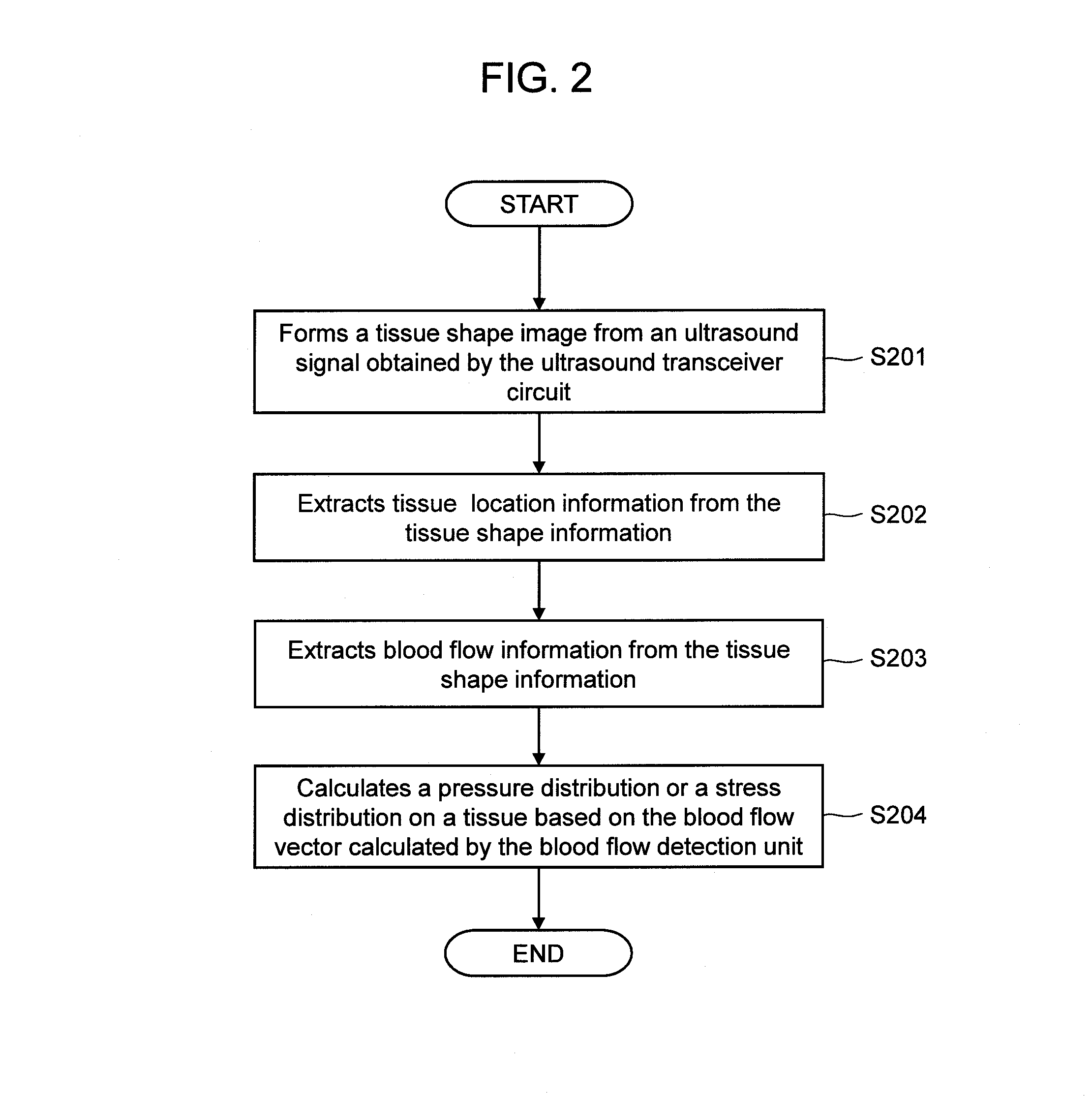
[0103]In the present invention, a specific example of step S204 in FIG. 2 will be described. The configuration of the ultrasound imaging device 1 is the same as that of the embodiments 1 and 2.
[0104]The mutual interaction calculation unit 153 calculates physical interactions between the biological tissues and the blood flows according to the tissue location information of the subject 3 obtained by the shape recognition unit 151 and the blood flow velocity vectors obtained by the blood flow detection unit 152. The mutual interaction mentioned here can be calculated from a mutual interaction of stress, momentum exchange, energy exchange, and the like.
[0105]Mutual interaction of stress can be generally categorized into a stress in a direction parallel to the normal of the tissue boundary and a shear stress in a direction perpendicular to the normal.
[0106]Pressure distributions can be calculated by motion equation of fluids. Navier-Stokes equation describing a law of conservation of mom...
PUM
 Abstract
Description
Claims
Application Information