Non-welded coping caps and transitions

a technology of transitions and coping caps, applied in the direction of paper/cardboard containers, transportation and packaging, adhesive types, etc., can solve the problems of difficulty in prefinished metal coping, lack of an equally exceptional method of providing coping system continuity, and high cost and relative poor performance with respect, so as to improve the coping cap and/or transition, improve the effect of coping system continuity, and adequate strength and durability of sheet joints

Active Publication Date: 2013-11-07
GARLAND INDS
View PDF28 Cites 2 Cited by
  • Summary
  • Abstract
  • Description
  • Claims
  • Application Information

AI Technical Summary

Benefits of technology

[0012]The present invention is directed to an improved coping cap and / or transition and a method of manufacturing the coping cap and / or transition that overcomes the problems associated with prior art coping caps and / or transitions. The improved coping cap and / or transition does not require a weld or solder, thus the adverse problems associated with coping caps and / or transitions that include a weld or solder are overcome. The improved coping cap and / or transition provides adequate strength and durability of the sheet joint for a coping cap. The improved coping cap and / or transition does not exhibit the undesirable discoloration that occurs with welding, soldering or other metal fusing methods for a coping cap. The improved coping cap and / or transition allows for the use of prepainted sheet metal produced by the continuous coil coating method which is more economical, durable, efficient, and better performing than other means of painting. The improved coping cap and / or transition does not required post-applied touch-up paints or other cosmetic corrections that will discolor over time at a different rate than the adjacent prepainted sheet materials. The improved coping cap and / or transition does not require costly equipment to post-apply and cure paint, thus the time required to cure post-applied paint is eliminated. The improved coping cap and / or transition does not require exposed mechanical fasteners to be used to secure sheet joints to one another.

Problems solved by technology

Traditional coping caps remain desirable for their aesthetic appeal, but due to their high cost and relatively poor performance with respect to weather tightness, stone, masonry, and pre-cast concrete coping caps have been largely replaced by continuous lengths (3 feet to 20 feet long, with 10 feet being most common) of sheet metal coping caps.
The Difficulty with Prefinished Metal Coping Systems
While prefinished metal coping systems offer significant performance, longevity, and aesthetic appeal at a moderate price, the systems currently lack an equally exceptional method of providing coping system continuity wherein two or more walls join, such as at a building corner.
Currently, there are a number of methods of joining the sheet metal together at the miter joint, each with an aspect rendering the miter unit inferior to the continuous lengths of metal coping away from the wall corner or transition.
This method can be accomplished with both bare and prefinished metals of all types, but results in a coping cap with visible, obtrusive fastener penetrations and possible sealant migration.
Although costly and requiring skilled craftsmen, the metal joint can be secured and sealed by fusing the metal together at the joint by one of these methods.
Galvanized or Galvalume® steel cannot be fused by these methods without dramatically increasing the risk of rust corrosion at the joint.
In the case of bare metals, this aesthetic anomaly is endured, as no better a solution currently exists.
While this eliminates several objections of the above mentioned methods, this is a generally cost prohibitive and time consuming process.
Furthermore, the post-applied paint systems use on average 500% more paint material, with more VOC release, and an overall lower level of performance when compared to the continuous coil coating method used for prefinished sheet metal.

Method used


Image

  • Non-welded coping caps and transitions
  • Non-welded coping caps and transitions
  • Non-welded coping caps and transitions

Examples


Embodiment Construction

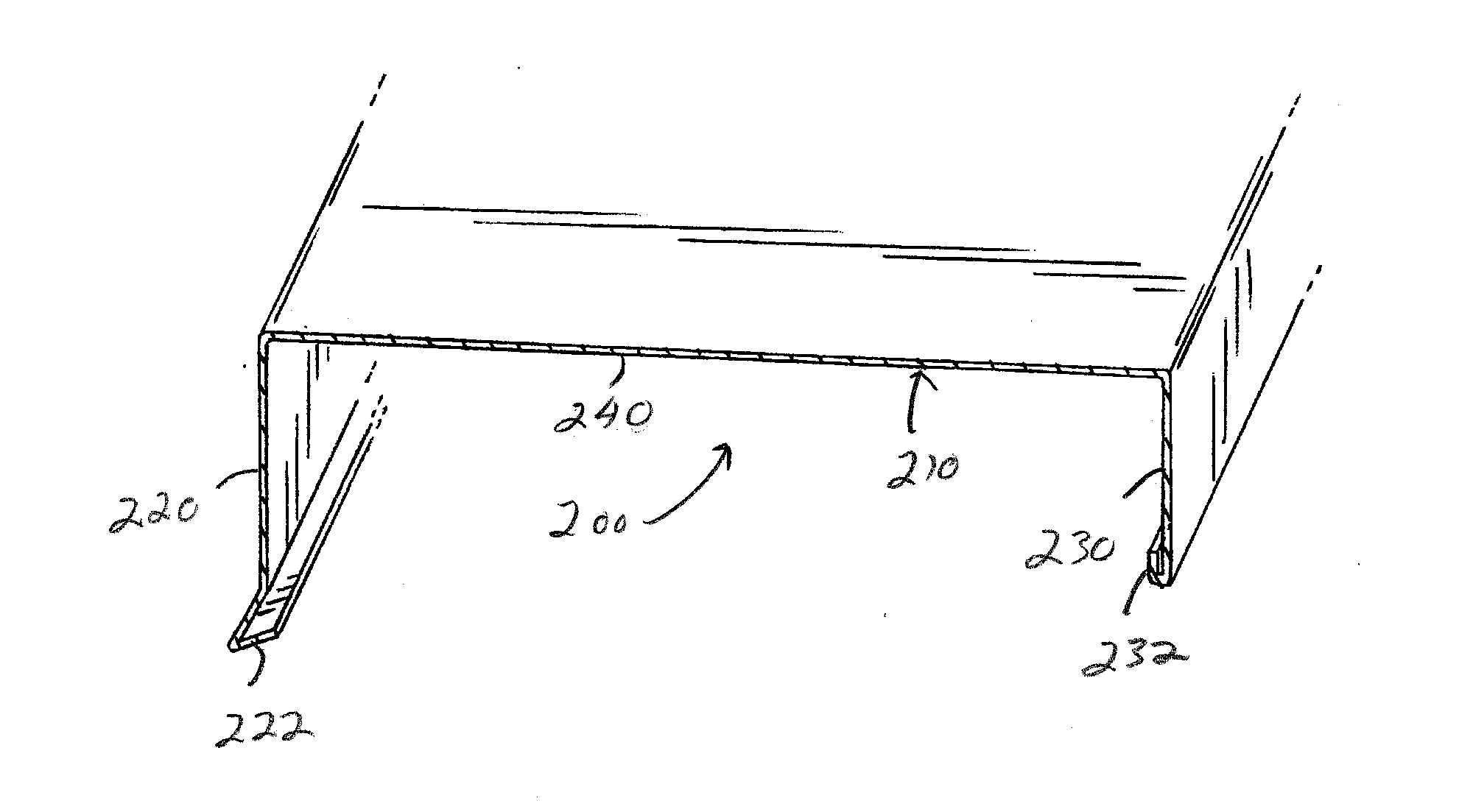
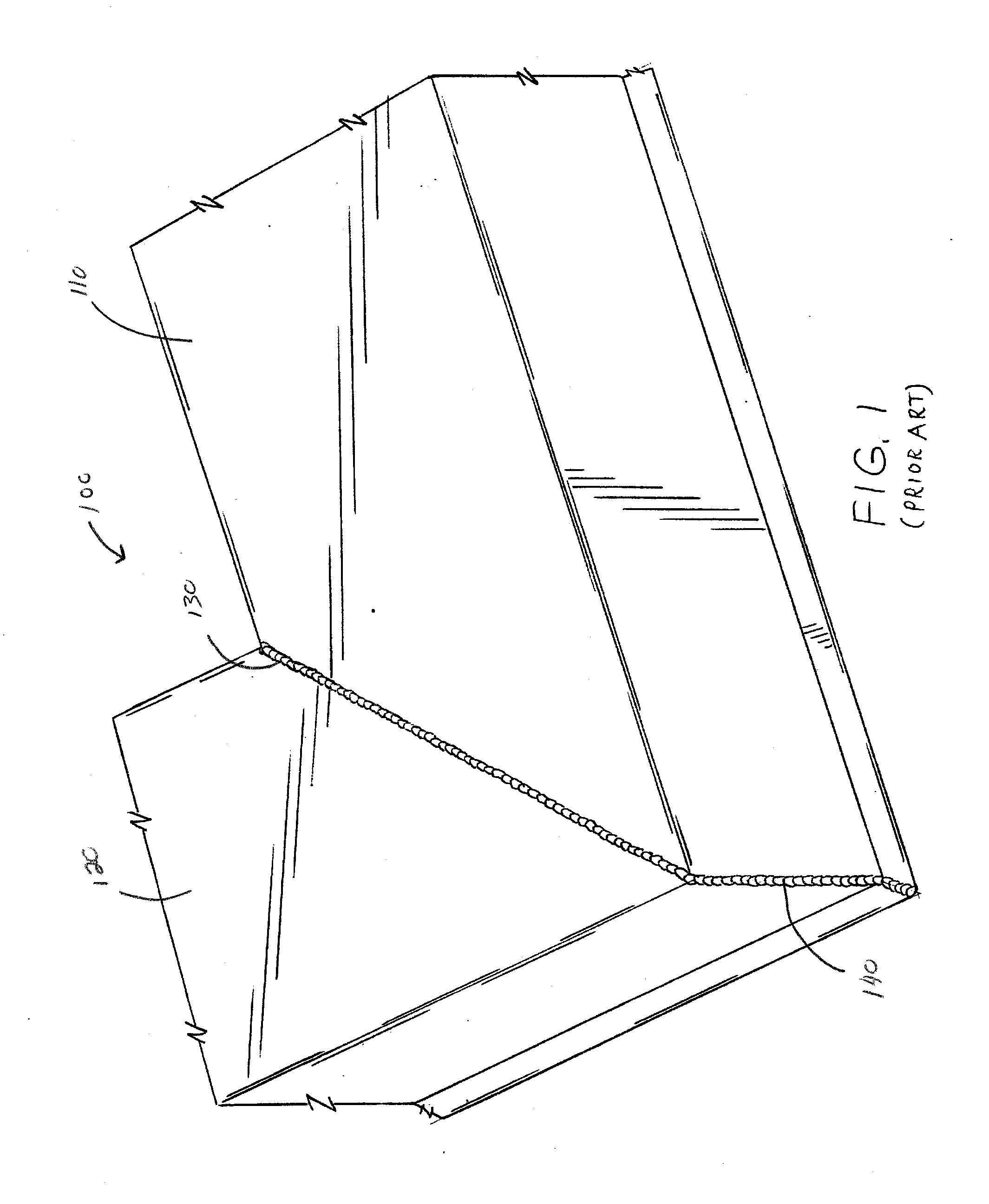
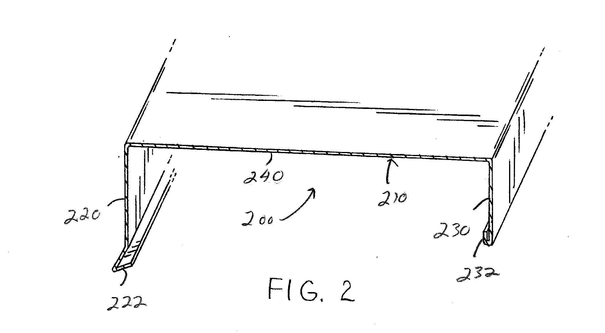
[0053]Referring now to the drawings, wherein the showings are for the purpose of illustrating preferred embodiments of the invention only and not for the purpose of limiting same, FIGS. 2-12 illustrate non-limiting configurations of a novel coping cap and a method for forming the novel coping cap in accordance with the present invention. The improved coping cap and / or transition does not require a weld or solder, thus the adverse problems associated with coping caps and / or transitions that include a weld or sold are overcome. As illustrated in FIG. 1, a prior art coping cap 100 is shown having a welded or solder seam 130, 140 on the exterior surface of the coping cap. The coping cap is formed of two pieces of material 110, 120 that are connected together by the selected or solder seam. The welded or solder seam 130 is used to weld together the exterior bottom portion of the coping cap and the welded or solder seam 140 is used to weld together the exterior front edge of the coping ca...


PUM

PropertyMeasurementUnit
angleaaaaaaaaaa
lengthsaaaaaaaaaa
lengthsaaaaaaaaaa

Abstract

A design and fabrication technique whereby a coping cap and/or transition can be supplied with mitered corner sections and other transitional components which utilize the identical prefinished or bare sheet metal material(s) without any reliance on exposed mechanical fasteners, welding, soldering, or post-applied paints. This is essentially accomplished by joining the pre-finished sheet material(s) together using a mesh screen and adhesive on the underside (non-exposed) face of the sheet material(s).

Description

[0001]The present invention claims priority on U.S. Provisional Patent Application Ser. No. 61 / 642,718 filed May 4, 2012, which is incorporated herein.[0002]The present invention is directed to the building industry, particularly to coping systems for buildings, and more particularly to a coping system that includes mitered corner sections and other transitional components without any reliance on exposed mechanical fasteners, welding, soldering, or post-applied paints.BACKGROUND OF THE INVENTION[0003]Many, if not a majority, of commercial buildings are constructed with flat roofs with raised parapet walls around the building perimeter and at other locations within the footprint of the roof. Traditionally, the top of the parapet wall has been terminated and sealed with a cut stone, masonry, or precast concrete coping cap set in mortar and / or sealant. Some purposes of the coping cap are to aesthetically accent the top of the wall, and to seal the wall cavity from moisture infiltration...

Claims


Application Information

Patent Timeline
Patent Type & Authority Applications(United States)
IPC IPC(8): E04D3/40C09J5/00
CPCE04D3/405C09J5/00Y10T156/10Y10T428/19
Inventor RESSO, FRANKNELSON, RON
Owner GARLAND INDS
Why Eureka
Try Eureka