
Resonance-based wireless power transfer system

a wireless power transfer and wireless technology, applied in the direction of transformers/inductance circuits, circuit arrangements, inductances, etc., can solve the problems of supplying electrical power to implants within biological bodies (e.g., a human or an animal), remained a significant problem, and involves high cost and surgical risks. , to achieve the effect of being easily adjusted

Active Publication Date: 2013-11-07
HUAZHONG UNIV OF SCI & TECH +1
View PDF15 Cites 71 Cited by
  • Summary
  • Abstract
  • Description
  • Claims
  • Application Information

AI Technical Summary

Benefits of technology

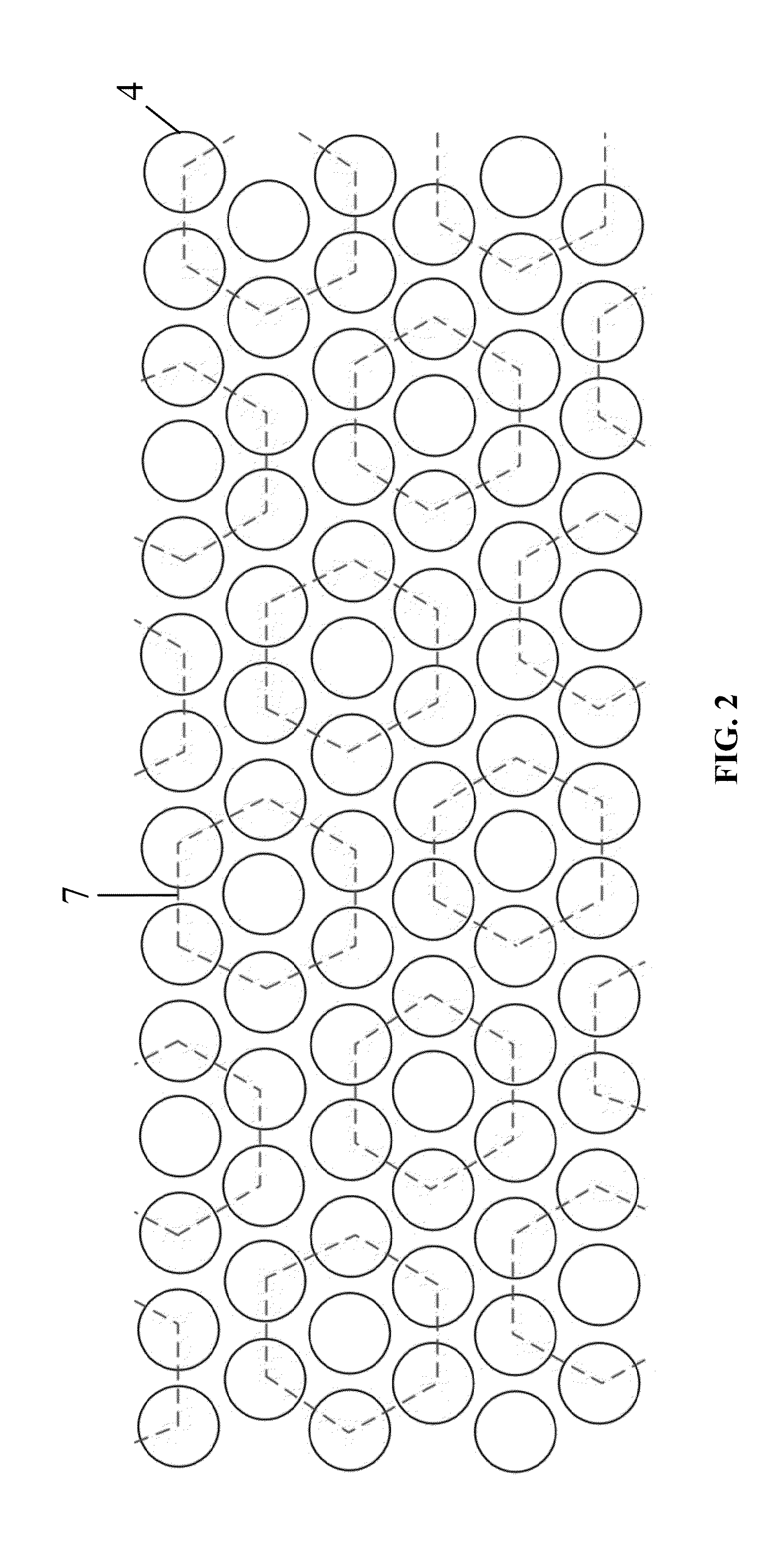
The patent text describes different coil designs for use in transmitters and receivers. One design utilizes a circular or hexagonal spiral coil shape, which allows for flexibility in building experimental stations of different sizes and shapes. Another design includes a secondary coil with a shallow box shape that serves as a packaging cover for the implant and a power receiver coil, allowing for smaller device size and weight. The text also discusses a power mat with multiple hexagonal cells that each contain a group of spiral coils. The cells can be designed with different sizes and patterns of conductor strips to adjust their resonant frequencies and Q-factors. These different coil designs offer flexibility and performance enhancement at radio frequencies while also minimizing device size and weight for implantation without affecting the subject's mobility.

Problems solved by technology

However, supplying electrical power to implants within a biological body (e.g., a human or an animal) has remained a significant problem.
Despite improvements in energy density of implantable batteries, periodic surgeries are still required to replace a depleted battery, which involves high cost and surgical risks.
On the other hand, for artificial hearts with high power requirement, energy is commonly provided by external batteries through percutaneous wires susceptible to infection and a limited range of movement.
In cases where rechargeable batteries are used to support implants, successful application is currently limited as a result of various issues related to the size, weight, longevity, toxicity and safety of batteries.
Up to the present, based on magnetic coupling, the amount of wireless power that can be delivered transcutaneously to the animal in a reliable fashion has been too small for most stimulation implants, and the feasibility of performing WPT while allowing free motion of the laboratory animal within a relatively large experimental site has remained unproven.
However, in order for wireless electricity to be used for powering implanted medical devices, the user must always carry a radio frequency amplifier and wear transmitter coils, posing major restrictions on his / her free movement.
This is inconvenient as well as unsuitable for experimental animals.

Method used


Image

  • Resonance-based wireless power transfer system
  • Resonance-based wireless power transfer system
  • Resonance-based wireless power transfer system

Examples


Embodiment Construction

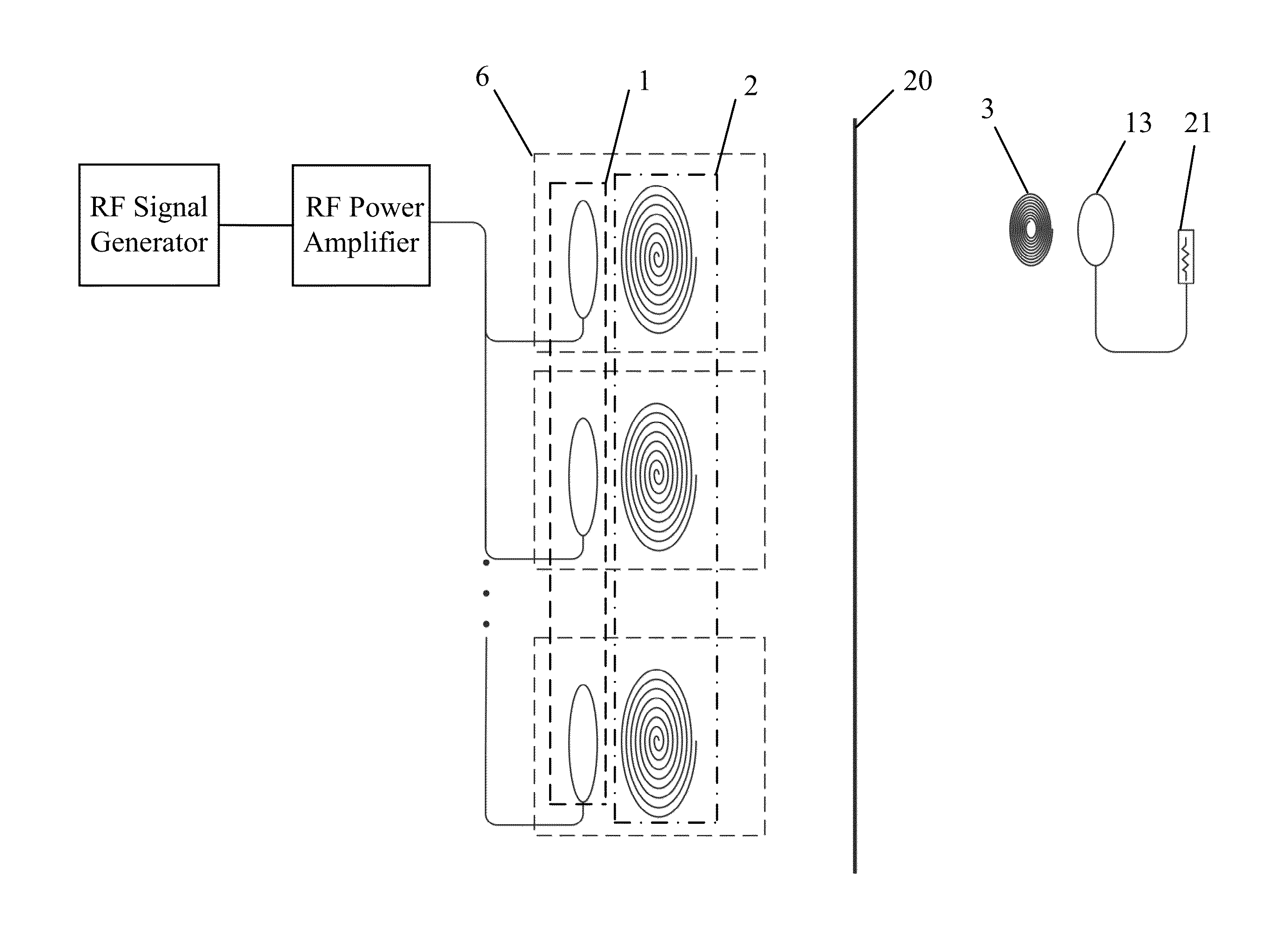
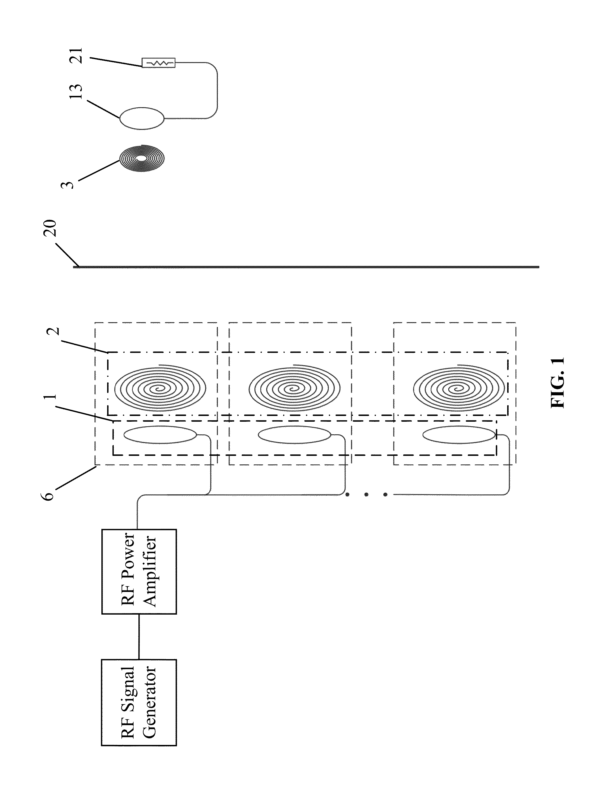
[0029]FIG. 1 is a block diagram of a wireless electricity system according to one embodiment of the invention. As described in greater detail elsewhere herein, the wireless electricity system allows power to be transferred wirelessly from a source to a load based on the concept of evanescent resonant coupling mediated through the overlap of the nonradioactive near (e.g., magnetic) fields of two resonators (referred to as nonradioactive resonant coupling). In particular, in the scheme employed by the wireless electricity system, the coupling is implemented by the evanescent lossless stationary near-field rather than the lossy radiative far-field.

[0030]Referring to FIG. 1, the wireless electricity system for powering a medical implant comprises an RF signal generator operatively connected to a power amplifier. The RF signal generator generates an RF energy signal, which is amplified by the power amplifier to provide amplified RF energy signal. The wireless electricity system also comp...


PUM


Abstract

A wireless power transfer system including a driver coil array, a hexagonally-packed transmitter mat, a receiver coil, and a load coil for powering a medical implant. The magnetically coupled resonance between two isolated parts is established by an array of primary coils and a single small secondary coil to create a transcutaneous power link for implanted devices as moving targets. The primary isolated part includes a driver coil array magnetically coupled to a mat of hexagonally packed primary coils. Power is injected by the driver coils into the transmitter coils in the transmitter mat to maintain resonance in the presence of losses and power drawn by the receiver coil from the magnetic field. The implanted secondary isolated part includes a receiver coil magnetically coupled to a load coil. A rectification / filter system is connected to the load coil supplying DC power to the electronic circuits of the implant.

Description

CROSS-REFERENCE TO RELATED APPLICATIONS[0001]Pursuant to 35 U.S.C. §119 and the Paris Convention Treaty, this application claims the benefit of Chinese Patent Application No. 201210104018.7 filed Apr. 11, 2012, the contents of which are incorporated herein by reference. Inquiries from the public to applicants or assignees concerning this document or the related applications should be directed to: Matthias Scholl P.C., Attn.: Dr. Matthias Scholl Esq., 14781 Memorial Drive, Suite 1319, Houston, Tex. 77079.BACKGROUND OF THE INVENTION[0002]1. Field of the Invention[0003]The invention relates to the wireless delivery of energy, and in particular to a wireless power transfer system that allows energy, such as RF energy, to be transferred wirelessly to moving targets using nonradioactive resonant coupling.[0004]2. Description of the Related Art[0005]In recent years, rapid technological advances in microelectronics, nanotechnology and MEMS technology have spurred new types of implanted devi...

Claims


Application Information

Patent Timeline
IPC IPC(8): H01F38/14
CPCH01F38/14A01K1/031A01K11/006H02J50/12H02J50/90H02J50/402
Inventor XU, QISUN, MINGUIWANG, HAOMAO, ZHIHONGHE, JIPING
Owner HUAZHONG UNIV OF SCI & TECH
Learn More