Switching converter

Inactive Publication Date: 2013-11-07
SKY SOCKET +1
View PDF8 Cites 15 Cited by
  • Summary
  • Abstract
  • Description
  • Claims
  • Application Information

AI Technical Summary

Benefits of technology

[0016]In one embodiment of the present invention, a transistor and a resistor each including a wide-gap semiconductor are used as a transistor and a resistor included in a starter circuit that controls startup of a control circuit, whereby detrioration and breakage of

Problems solved by technology

However, the starter switch, main switch, starting resistor, and the like have problems of deterioration and breakage because a high voltage is applied thereto from a

Method used


Image

  • Switching converter
  • Switching converter
  • Switching converter

Examples


embodiment 1

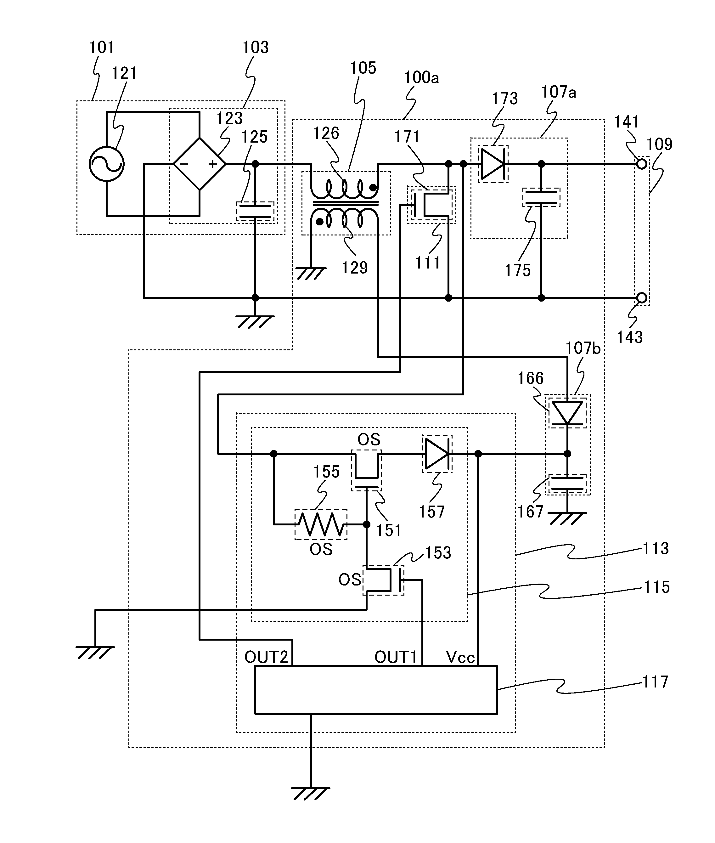
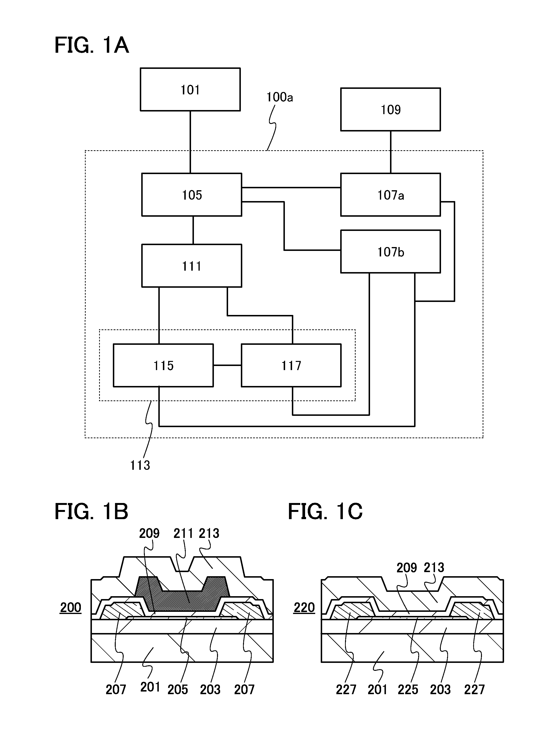
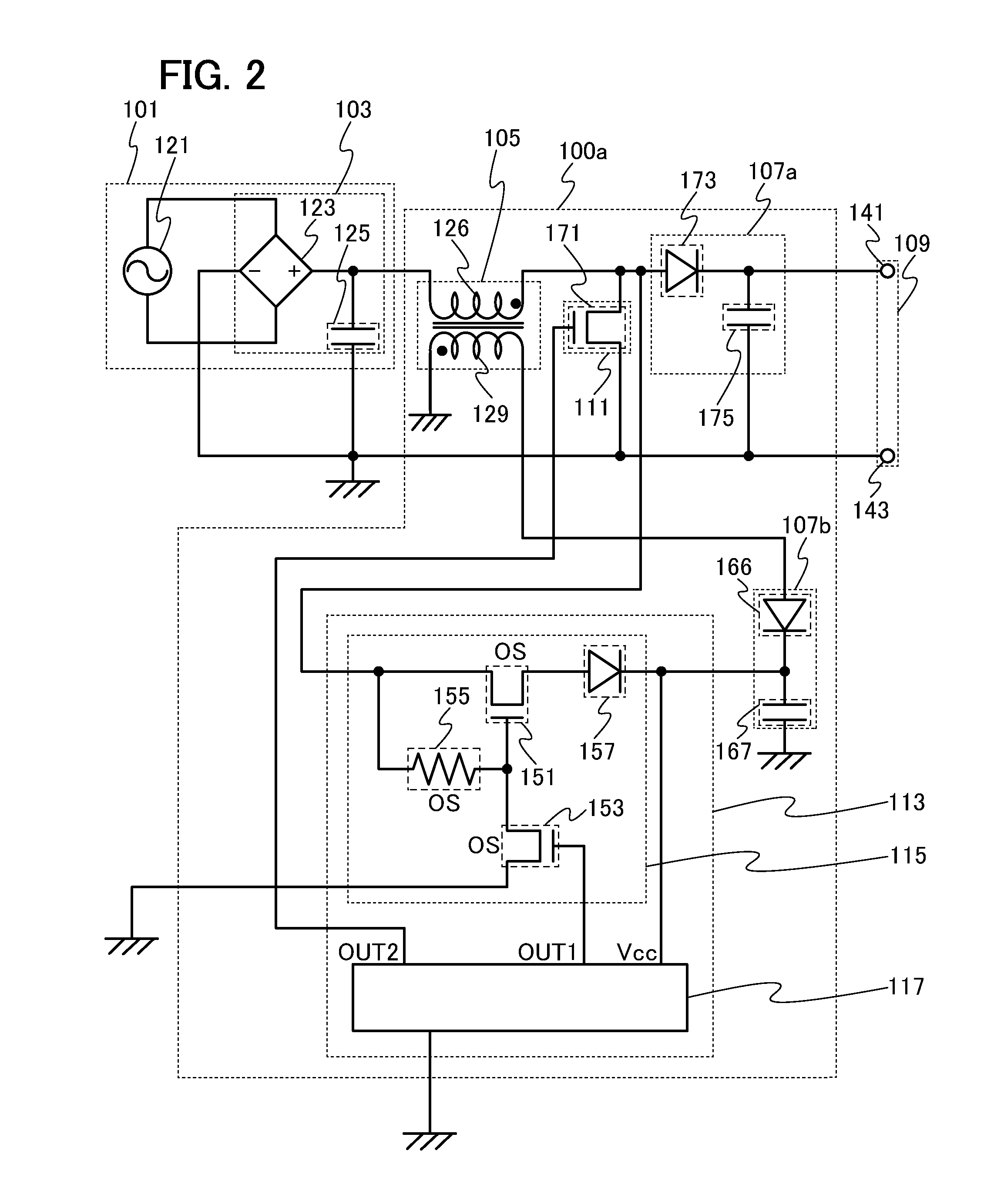
[0042]A structure of a switching converter of one embodiment of the present invention will be described with reference to FIGS. 1A to 1C, FIG. 2, FIG. 3, and FIG. 4. In this embodiment, a structure of a non-isolated switching converter will be described.

[0043]A switching converter 100a illustrated in FIG. 1A generates a constant voltage (output voltage) using a voltage (input voltage) supplied from a power supply portion 101, and outputs the constant voltage from an output portion 109.

[0044]The switching converter 100a includes a transformer 105, a rectifying and smoothing circuit 107a, a rectifying and smoothing circuit 107b, a switch 111, and a switching control circuit 113. Note that the transformer 105 is connected to the power supply portion 101. The rectifying and smoothing circuit 107a is connected to the output portion 109.

[0045]The switching control circuit 113 includes a starter circuit 115 and a control circuit 117.

[0046]The transformer 105 is connected to the rectifying ...

embodiment 2

[0117]A structure of a switching converter of one embodiment of the present invention will be described with reference to FIG. 11 and FIG. 12. In this embodiment, a structure of an isolated switching converter will be described.

[0118]A switching converter 180 illustrated in FIG. 11 includes the transformer 105, the rectifying and smoothing circuit 107a, the rectifying and smoothing circuit 107b, the switch 111, and the switching control circuit 113. Note that the transformer 105 is connected to the power supply portion 101. The rectifying and smoothing circuit 107a is connected to the output portion 109.

[0119]The transformer 105 includes a transformer 105a and a transformer 105b. The switching control circuit 113 includes the starter circuit 115 and the control circuit 117.

[0120]The transformer 105a is connected to the rectifying and smoothing circuit 107a and the switch 111. The transformer 105b is connected to the rectifying and smoothing circuit 107b and the switch 111.

[0121]The ...

embodiment 3

[0164]In this embodiment, a structure of the switching control circuit 113 included in the switching converter 180 will be described with reference to FIGS. 19A and 19B. FIGS. 19A and 19B are cross-sectional diagrams of a CMOS (complementary metal oxide semiconductor) circuit which includes the transistor 151, the transistor 153, the resistor 155, the diode 157, and the control circuit 117 in the switching control circuit 113 illustrated in FIG. 12.

[0165]FIG. 19A is the cross-sectional diagram of a switching control circuit 760. The switching control circuit 760 including the starter circuit 115 and the control circuit 117 is provided over a grounded member 761. The switching control circuit 760 includes an element layer 763a and an element layer 763b. The element layer 763a includes a transistor and a diode (typically, the diode 157 included in the starter circuit 115 in Embodiment 1 and Embodiment 2) which are formed using a semiconductor substrate, and the like. The element layer...


PUM


Abstract

A switching converter in which deterioration and breakage can be suppressed is provided. A switching converter whose area can be reduced is provided. The switching converter includes a switch connected to a power supply portion; a transformer connected to the power supply portion; a first rectifying and smoothing circuit and a second rectifying and smoothing circuit each connected to at least the transformer; and a switching control circuit which is connected to the first rectifying and smoothing circuit and the second rectifying and smoothing circuit and which controls operation of the switch. The switching control circuit includes a control circuit controlling on/off of the switch and operation of a starter circuit; and the starter circuit controlling startup of the control circuit. The starter circuit includes a transistor and a resistor each including a wide-gap semiconductor.

Description

BACKGROUND OF THE INVENTION[0001]1. Field of the Invention[0002]The present invention relates to a switching converter and a semiconductor device.[0003]2. Description of the Related Art[0004]A switching converter is a constant-voltage circuit with which a constant output voltage can be obtained regardless of the value of an input voltage, and the switching converter is used for a power supply circuit together with a rectification circuit or the like. In particular, a power supply circuit including a switching converter is also referred to as switching power source or switching regulator.[0005]The switching type switching converter outputs a voltage of a predetermined level in such a manner that a voltage with a pulse waveform is formed using an input voltage by a switching element and the voltage is smoothed or held in a coil, a capacitor, or the like. With the switching type switching converter, internal power loss can be lower theoretically, whereby the power conversion efficiency...

Claims


Application Information

Patent Timeline
IPC IPC(8): H02M1/36
CPCH02M1/36H02M3/335H02M3/33507H02M3/33523H02M7/517H02M1/0006
Inventor NOMURA, MASUMINODA, KOSEI
Owner SKY SOCKET
Why Eureka
Try Eureka