Intraluminal device and method

a technology of intraluminal device and stent, which is applied in the field of intraluminal device and method, can solve the problems of scaring or fibrosis, stenosis or stricture, irritation and inflammation of innermost tissue, etc., and achieve the effect of reducing or eliminating stenosis or strictur

Inactive Publication Date: 2013-11-07
BFKW
View PDF7 Cites 29 Cited by
  • Summary
  • Abstract
  • Description
  • Claims
  • Application Information

AI Technical Summary

Benefits of technology

[0003]The present invention is directed to an intraluminal device and method that can reduce or ...

Problems solved by technology

It is believed that the spasm results in micro-tears in the innermost tissue of the lumen which causes irritation and infl...

Method used


Image

  • Intraluminal device and method
  • Intraluminal device and method
  • Intraluminal device and method

Examples


Embodiment Construction

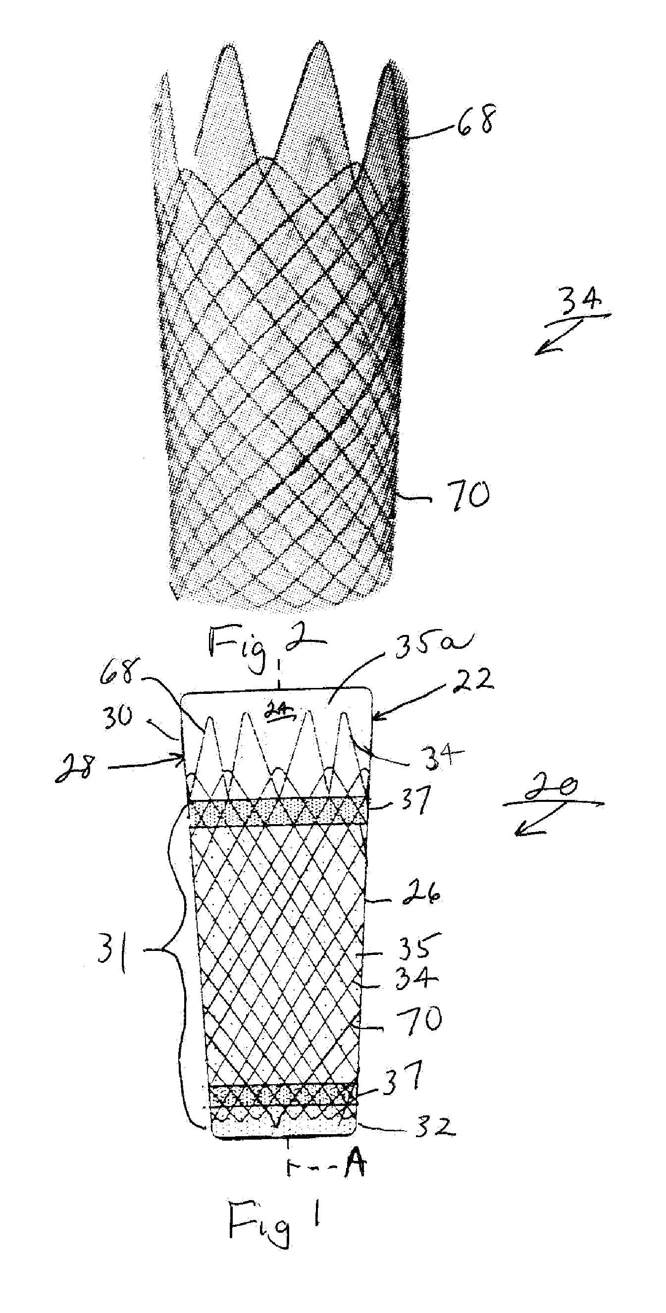
[0028]Referring now to the drawings and the illustrative embodiments depicted therein, an intraluminal device 20 includes an intraluminal member, such as an esophageal member, 22 having a surface 24 that is defined by a wall 26 having opposite end portions made up of a proximal portion 30 and a distal end portion 32 (FIGS. 1 and 2). Surface 24 is configured to generally conform to the shape and size of a portion of the lumen (not shown) of the recipient in which it is to be deployed. In particular, surface 24 is configured to generally conform to the shape and size of a portion of a lumen that experiences peristalsis. Examples of such a lumen include the esophagus, the colon, other portions of the intestines, ureter, urethra, biliary duct, fallopian tube, vas deferens, and the like. End portions 30, 32 are spaced apart along an axis A, which is the direction of peristaltic movement along the lumen in which device 20 is deployed. Wall 26 is defined by a support structure, such as a w...


PUM


Abstract

An intraluminal device and method includes positioning an intraluminal device in the recipient including positioning the intraluminal device in a lumen that experiences peristalsis. The intraluminal device has a surface defined by a wall. The surface is configured to generally conform to the shape and size of a portion of the lumen. The wall is adapted to reduce luminal spasm resulting from the peristalsis.

Description

BACKGROUND OF THE INVENTION[0001]The present invention is directed to an intraluminal device and method and, in particular, to such a device and method that are useful in a lumen that is subject to peristalsis waves. The invention may be applied to a bariatric device and method of causing at least partial satiety in a recipient of the device and in particular to a bariatric device and method having an esophageal component. However, the invention may find various applications in other lumens that are subject to peristalsis.[0002]Placement of an intraluminal device in a lumen that is subject to peristalsis may lead to stenosis or stricture of the underlying muscle.SUMMARY OF THE INVENTION[0003]The present invention is directed to an intraluminal device and method that can reduce or eliminate stenosis or stricture from deployment of the device in a lumen that experiences peristalsis.[0004]An intraluminal device and method, according to an aspect of the invention, includes positioning a...

Claims


Application Information

Patent Timeline
IPC IPC(8): A61F5/00
CPCA61F5/0076A61F2/04A61F2/07A61F6/20A61F2002/044A61F2002/828A61F2230/0067A61F2250/0039A61F5/0013
Inventor FOOTE, JAMES A.WALBURN, FREDERICK J.BAKER, RANDAL S.
Owner BFKW
Why Eureka
Try Eureka