
Simulation and control system and method using contact, pressure waves and factor controls for cell regeneration, tissue closure and related applications

a control system and cell technology, applied in the field of simulation and control system and method using contact, pressure waves and factor control for cell regeneration, tissue closure and related applications, can solve the problems of inability to fully realize the effect of cell regeneration

Active Publication Date: 2013-06-13
ZAM RES
View PDF6 Cites 19 Cited by
  • Summary
  • Abstract
  • Description
  • Claims
  • Application Information

AI Technical Summary

Benefits of technology

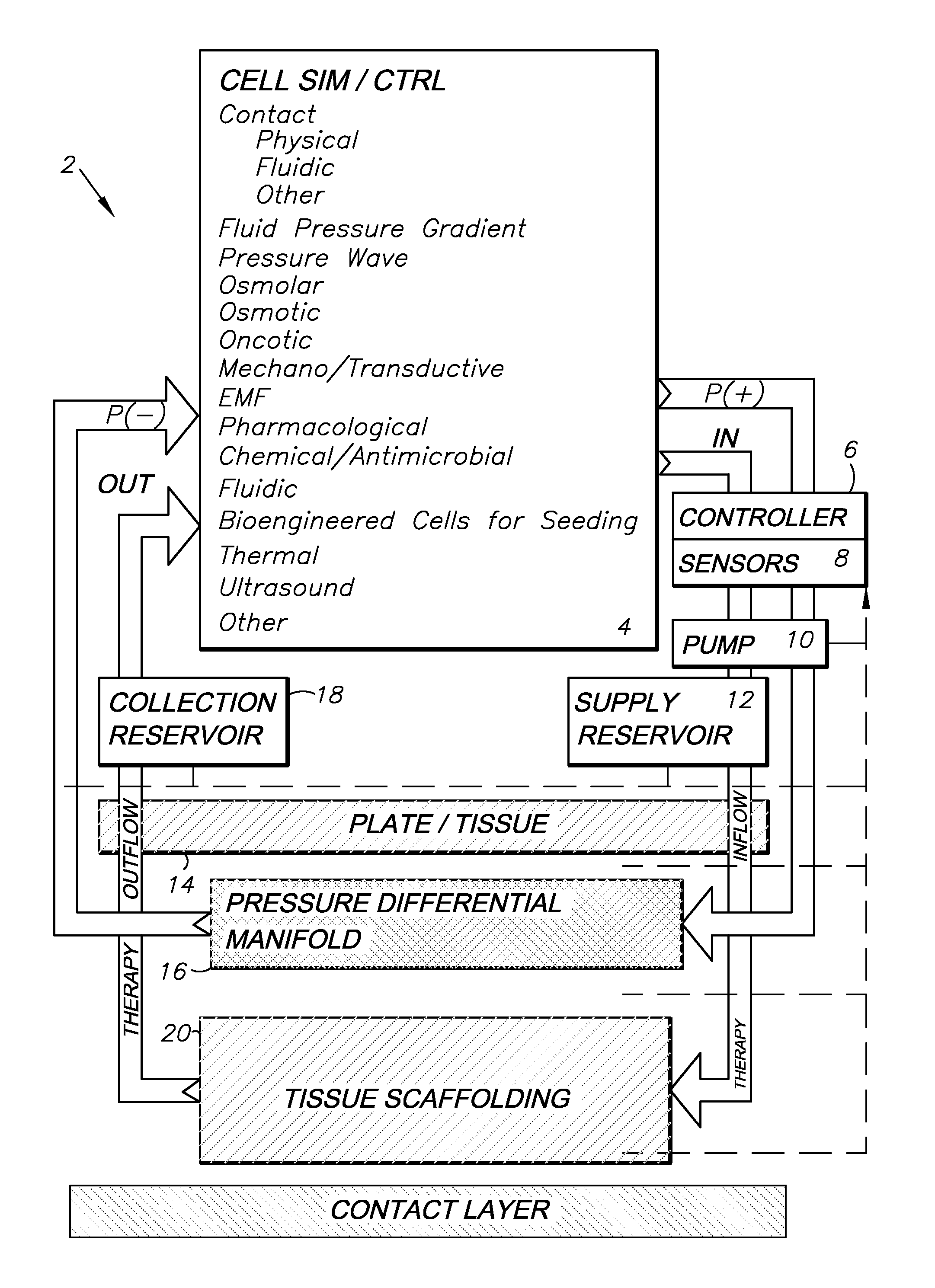
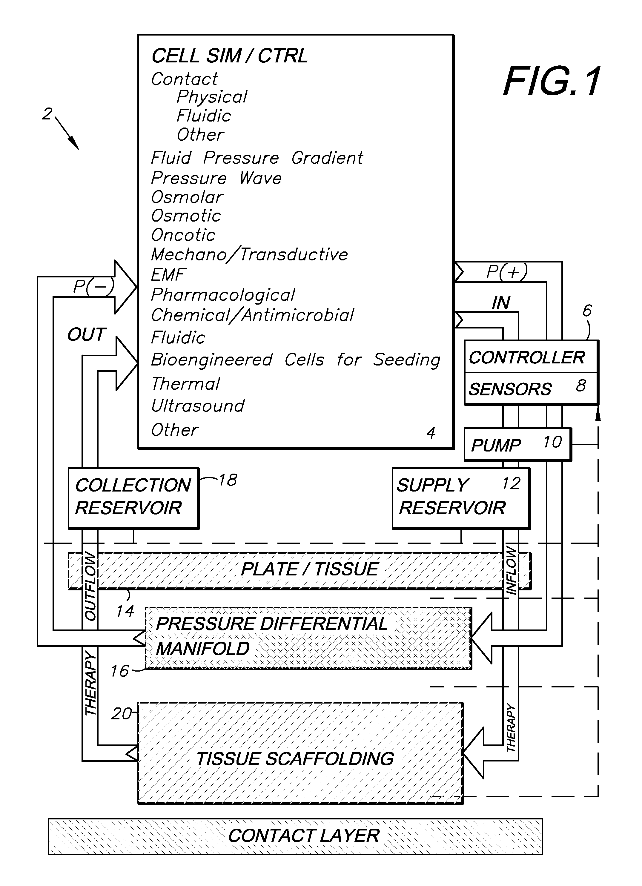
The invention relates to a method for simulating and controlling cellular contacts through the application of various factors such as contact relationships and forces. This method enhances and protects both migration and maturation of epithelialization without disrupting the fragile layer by promoting epithelium growth and facilitation of healing by removing excess air or moisture and adding clean air, moisture, or other elements which enhance healing. The method also uses vacuum pumps to balance air and moisture levels at the wound-site and may provide negative pressure to press the dressing against the wound and enhance healing.

Problems solved by technology

It is extremely challenging to get in vivo, invasive or non-invasive, instrumentation into these systems at microscopic levels and to sort out the intertwined signals and messages of this complex network of vessels and pulses and flows.
However, we know that without a pulsating arterial system, flow ceases or is very ineffective in this early lymphatic collection.
However, this practice was often limited to use with incisions smaller than one inch, as the thin foam is incapable of managing a large amount of exudates for a large, fresh wound, and if exudates accumulate under the foam piece the foam will lose surface contact, which allows bacteria to build up.
An injury to the vascular system typically results in clotting due to the exposed red blood cells, which controls bleeding.
Lymph fluid, however, lacks comparable coagulating properties.
Moreover, the lymphatic circulatory system lacks the muscled walls of the vascular circulatory system.
Unlike the quick response of coagulating red cells, lymphatic circulatory system closure tends to be slower and can take days.

Method used


Image

  • Simulation and control system and method using contact, pressure waves and factor controls for cell regeneration, tissue closure and related applications
  • Simulation and control system and method using contact, pressure waves and factor controls for cell regeneration, tissue closure and related applications
  • Simulation and control system and method using contact, pressure waves and factor controls for cell regeneration, tissue closure and related applications

Examples


embodiment a

IV. Embodiment A

[0046]This represents the least constrained model. The gel medium is rendered by utilizing synthetic or engineered dynamic gel. This provides the opportunity to cut the material to insert sensors and to shape the material by warming and pouring into containers that produce the desired shape and size for testing. The gel can then be removed from the shaping container and left with just the dependent surface in contact with the supporting structure or the gel can be supported in planned percentages of circumference by netting or slinging.

[0047]The internal liquid phase can be simulated by elastic tubing (e.g. Penrose Drain latex tubing in various widths) extended beyond the surface of the gel allowing measured addition, pressurization, pulsation and removal from an external access point to the tubing. This can be placed, as can the sensors, by cutting the gel at the desired point(s) or by pouring the gel to that point, allowing some cooling, laying on of the tubing / sen...

embodiment b

V. Embodiment B

[0051]This is the most constrained model. Of course, all permutations between A and B are feasible. This model consists of an appropriate rigid material, like acrylic or some other plastic or metal (even the container that the ballistic gel is melted in), that forms the sides of this model. For the example of this embodiment we choose a square shape and rigidly supply 5 of the 6 walls of the cube. The gel is prepared, whole, cut or layered as described above, and poured or placed in the container (or the container can be built around the gel). “Through-hull” type fittings are fashioned with the gel flush with the internal or external portion of the walls and the above described tubing, measuring devices and mechanical force impounder are fitted through them. For example, the lines of the sensors can be run up the walls and over the top of the container or lead out through holes in the wall. A mechanical force piston can be fit in such a hole and separated from the gel...

embodiment c

VI. Embodiment C

[0053]This arrangement of components and sensors is like the rigid box in B, however the placement of tubing and sensors is exchanged. The (central) embedded (can either start collapsed or the anticipated average size be cored out of the gel) elastic tubing (utilizing as part of the testing various degrees of elasticity and rigidity) can be continuous throughout the length of the box, containing liquid in the tubing all the way throughout as it runs from input through output ports, ending at valves or sensors or pumps on the exterior of the box. Or it can end blindly in a blunt end within the gel inside the experimental box utilizing only a single port for administering or removing the liquid it contains and for passing the sensors. Instead of sensors in the gel as in Embodiment B, the sensors, e.g., a string of micro manometers in a catheter with the sensors placed every few centimeters or an elongated format for the Tecscan® force plate can be inserted inside the t...


PUM


Abstract

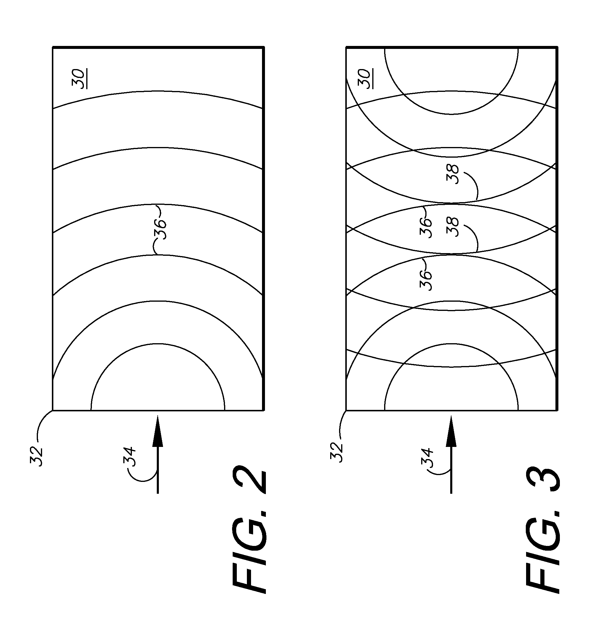
A description of a device and method of use are provided for a containment chamber, accompanying sensing and monitoring instrumentation, and method of creation of a physical force wave that would be capable of mimicking physiologic waves such as pulse pressure, muscle contraction, peristalsis, acoustic waves and other desired waves to be studied. This device allows for the use of various biologic or biologically comparable fluids—alone or in combination—that would allow for the analysis of the passage of these waves through these media. Singularly, this device also allows for the manipulation of the external constraints that mimic the containment of that media in vivo. This allows for the analysis of the effects on the nature of the wave, its reflections, potential augmentation or dampening that occur in conjunction with various selected external and internal (baffle) constraints that mimic those found in nature or in therapeutic interventions.

Description

CROSS-REFERENCE TO RELATED APPLICATION[0001]This application claims priority in and incorporates by reference U.S. Patent Application Ser. No. 61 / 569,439, filed Dec. 12, 2011.BACKGROUND OF THE INVENTION[0002]1. Field of the Invention[0003]The present invention relates generally to a device and method for simulating and analyzing transmitted physical force waves in diverse media, said media being comparable with various biological fluids and said device allowing for the control and manipulation of the various internal and external constraints controllably applied to that media.[0004]2. Description of the Related Art[0005]Biologic and physiologic systems for mammals have two circulations—the vascular and the lymphatic. At the terminal loops of these two systems we have all elements in close proximity, microscopically close. Previous physiologic studies of this terminal bed at microscopic level essentially just show summary effects, such as flow variations—and then, only in the vascula...

Claims


Application Information

Patent Timeline
IPC IPC(8): G06F17/50
CPCG06F17/5009A61M2205/3344A61M2205/332A61M1/0088G16H50/50G16B5/00A61M1/915G06F30/20
Inventor ZAMIEROWSKI, DAVID S.BUBB, STEPHEN K.BILLINGS, WADE M.HILDEBRANDT, PATRICK A.TOBABEN, ERIC J.
Owner ZAM RES
Learn More