Power transfer system
a power transfer system and power technology, applied in the direction of electric variable regulation, process and machine control, instruments, etc., can solve the problem of difficulty in increasing the degree of magnetic coupling of transformers, and achieve the effect of significantly reducing power loss
- Summary
- Abstract
- Description
- Claims
- Application Information
AI Technical Summary
Benefits of technology
Problems solved by technology
Method used
Image

Examples
first preferred embodiment
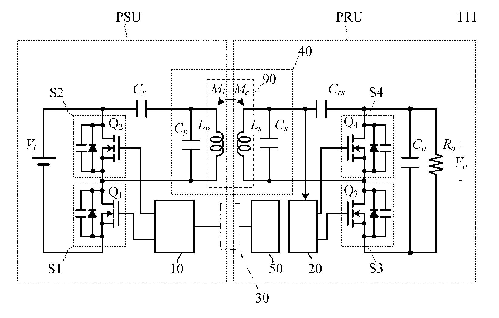
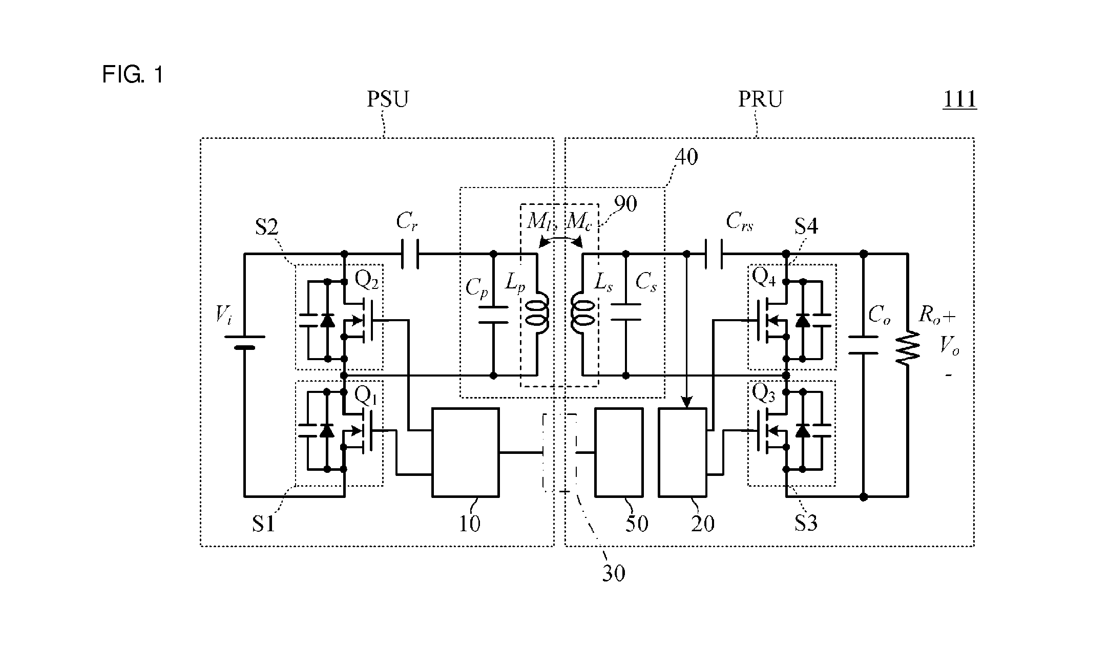
[0054]FIG. 1 is a circuit diagram of a power transfer system 111 according to a first preferred embodiment of the present invention.
[0055]The power transfer system 111 includes a power transmission unit PSU and a power reception unit PRU.
[0056]The power transfer system 111 is a system that includes an input power supply Vi provided at an input of the power transmission unit PSU and supplies stable direct-current energy to a load Ro of the power reception unit PRU. The power transfer system 111 includes the following components.
[0057]An electromagnetic coupling circuit 90 includes a power transmission coil Lp and a power reception coil Ls.
[0058]A switching circuit S1 includes a switching element Q1 and a switching circuit S2 including a switching element Q2 that are connected to the power transmission coil Lp.
[0059]A switching circuit S3 includes a switching element Q3, a switching circuit S4 including a switching element Q4, and a smoothing capacitor Co that are connected to the pow...
second preferred embodiment
[0138]FIG. 6 is a circuit diagram of a power transfer system 112 according to a second preferred embodiment. In this example, unlike the power transfer system 111 according to the first preferred embodiment, the power reception unit preferably includes rectifier diodes D3 and D4 instead of the switching elements Q3 and Q4 which serve as synchronous rectifier elements. That is, the diodes D3 and D4 constitute the power-reception-unit-side rectifier circuit.
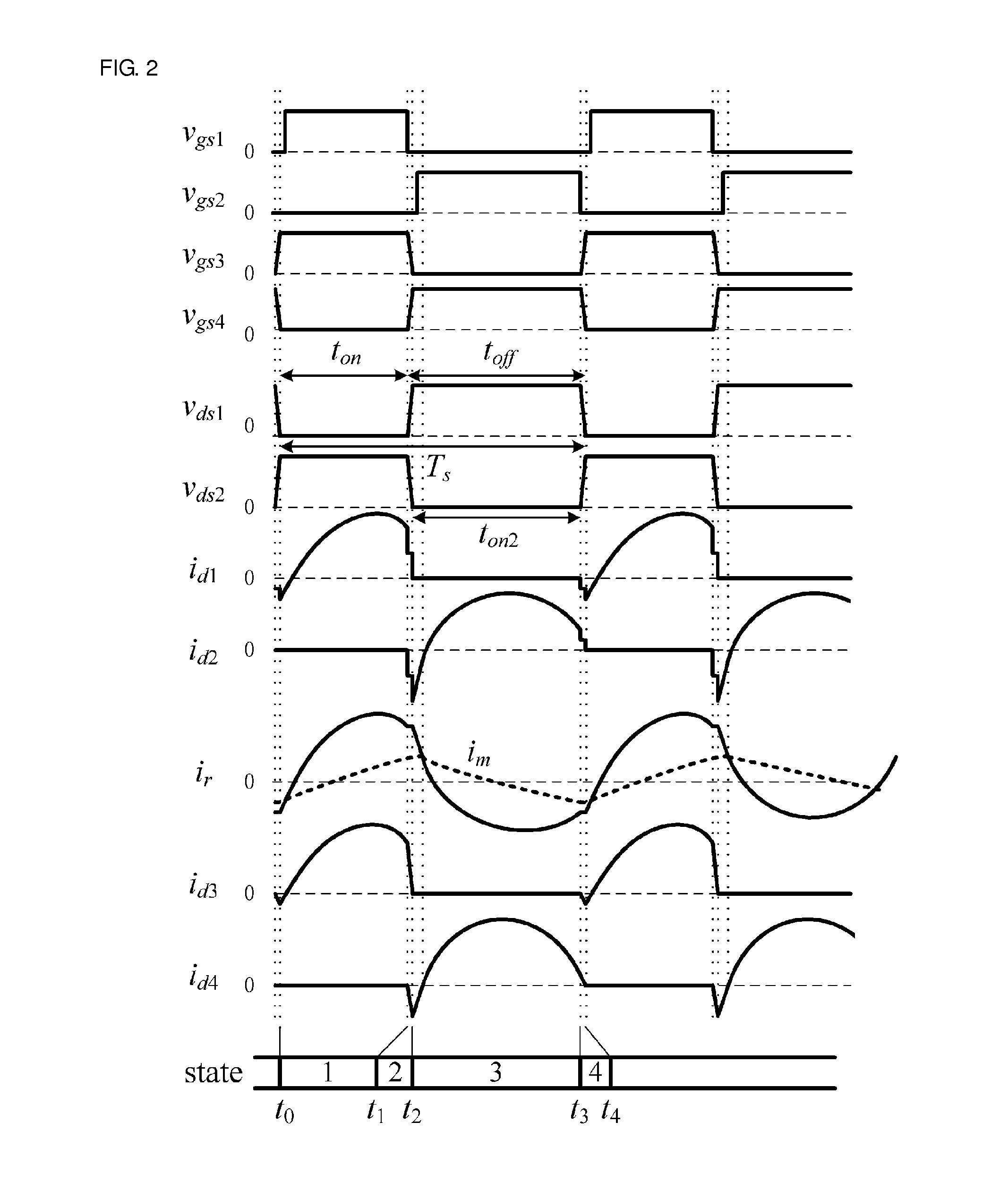
[0139]FIG. 7 is a diagram of voltage / current waveforms observed at corresponding components of the power transfer system 112 illustrated in FIG. 6. Operation of the power transfer system 112 at each timing is as follows.
[0140]Let im denote a magnetizing current of the power transmission coil Lp. Let vgs1 and vgs2 denote gate-source voltages of the switching elements Q1 and Q2, respectively. Let vds1 and vds2 denote drain-source voltages of the switching elements Q1 and Q2, respectively. The switching elements Q1 and Q2 are alternat...
third preferred embodiment
[0151]FIG. 8 is a circuit diagram of a power transfer system 113 according to a third preferred embodiment. A difference from the power transfer system illustrated in FIG. 1 in the first preferred embodiment is the configuration of the power reception unit PRU. In the third preferred embodiment, power reception coils Ls1 and Ls2, diodes D3 and D4, and a capacitor Co constitute a center-tap rectifier circuit. The configuration of the power transmission unit PSU is similar to that illustrated in the first preferred embodiment. However, at the power transmission unit PSU side, a parallel resonant capacitor Crsa (which is a capacitor equivalent to Cp in FIG. 1) is constituted by stray capacitance produced in the power transmission coil Lp or a discrete capacitor.
[0152]In this third preferred embodiment, at the power reception unit PRU side, a parallel resonant capacitor Crsb (which is a capacitor equivalent to Cs in FIG. 1) is constituted by stray capacitance produced in the power recep...
PUM
 Abstract
Description
Claims
Application Information
 - Generate Ideas
- Intellectual Property
- Life Sciences
- Materials
- Tech Scout
- Unparalleled Data Quality
- Higher Quality Content
- 60% Fewer Hallucinations
Browse by: Latest US Patents, China's latest patents, Technical Efficacy Thesaurus, Application Domain, Technology Topic, Popular Technical Reports.
© 2025 PatSnap. All rights reserved.Legal|Privacy policy|Modern Slavery Act Transparency Statement|Sitemap|About US| Contact US: help@patsnap.com