Electrowetting optical device

a technology of optical devices and conductive liquids, applied in the field of electrowetting optical devices, can solve the problems of reducing the difference in refractive index, excessive increase of the refractive index and reducing the number of chemical compounds or mixtures that can be used in the liquid to achieve all the above-cited requirements, so as to avoid excessive increase of the conductive liquid density, high density, and low miscibility

Active Publication Date: 2013-11-14
INVENIOS FRANCE SAS
View PDF3 Cites 3 Cited by
  • Summary
  • Abstract
  • Description
  • Claims
  • Application Information

AI Technical Summary

Benefits of technology

[0039]One of the advantages of using glycols in combination with salts as freezing-point lowering agents is to avoid an excessive increase of the conductive liquid density. Preferably, the conductive liquid density is below 1.2 g / cm3 at 20° C. For a given freezing point, a solution of salt and water has comparably a higher density than a solution of glycols and water. Glycols having compounds such as R—(OH)2, R being an alkyl group, preferably a C2-C4 alkyl, are preferably used. Such glycols show a low miscibility with components of the non-conductive liquid, and thus they do not compromise the electrowetting device reliability.
[0040]Another advantage of using glycols in the conductive liquid is that they act as viscosity-controlling agents. The viscosity is related to the response time of the electrowetting optical device, and controlling viscosity, in particular lowering viscosity provides rapid electrowetting optical devices with short response time.

Problems solved by technology

The number of chemical compounds or mixture of compounds that can be used in the liquids and reaching all the above cited requirements is very limited.
A drawback with known prior art is an excessive increase of the refractive index of the conductive liquid when comprising salts as anti-freezing agents.
Since the conductive liquid has preferably a refractive index lower than the refractive index of the non-conductive liquid, the use of salts as freezing point lowering agents according to the prior art tends to decrease the difference in refractive index between the conductive and the non-conductive liquids, which is undesirable in many applications, such as for example in zoom applications.
Another drawback with known prior art on optical electrowetting device such as optical lenses or zooms is the degradation of the optical performance of the device due to chromatic aberrations that can lead to blurred images.
In particular, increasing the amount of salts can lead to an increase of the chromatic aberrations.
In the case of a lens, chromatic aberrations are the failure of a lens to focus all colors to the same point.
Chromatic aberrations can be a problem difficult to overcome in optical design, especially when using for example an optical electrowetting device wherein the optical power is changing according to the application of a voltage, thus providing variable chromatic aberrations.
This problem can be even greater for zoom applications wherein a large optical power variation is required, for example a zoom where the zoom function is provided by an optical electrowetting device having a large optical power variation, for example a device with the two liquids forming the optical interface by having a high refractive index difference.

Method used


Image

  • Electrowetting optical device
  • Electrowetting optical device
  • Electrowetting optical device

Examples


Embodiment Construction

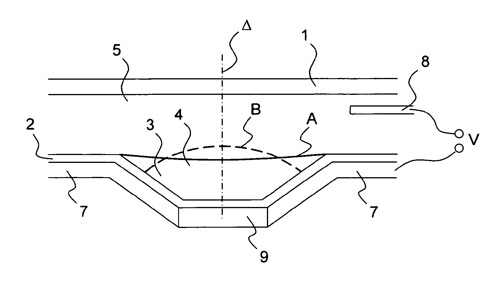
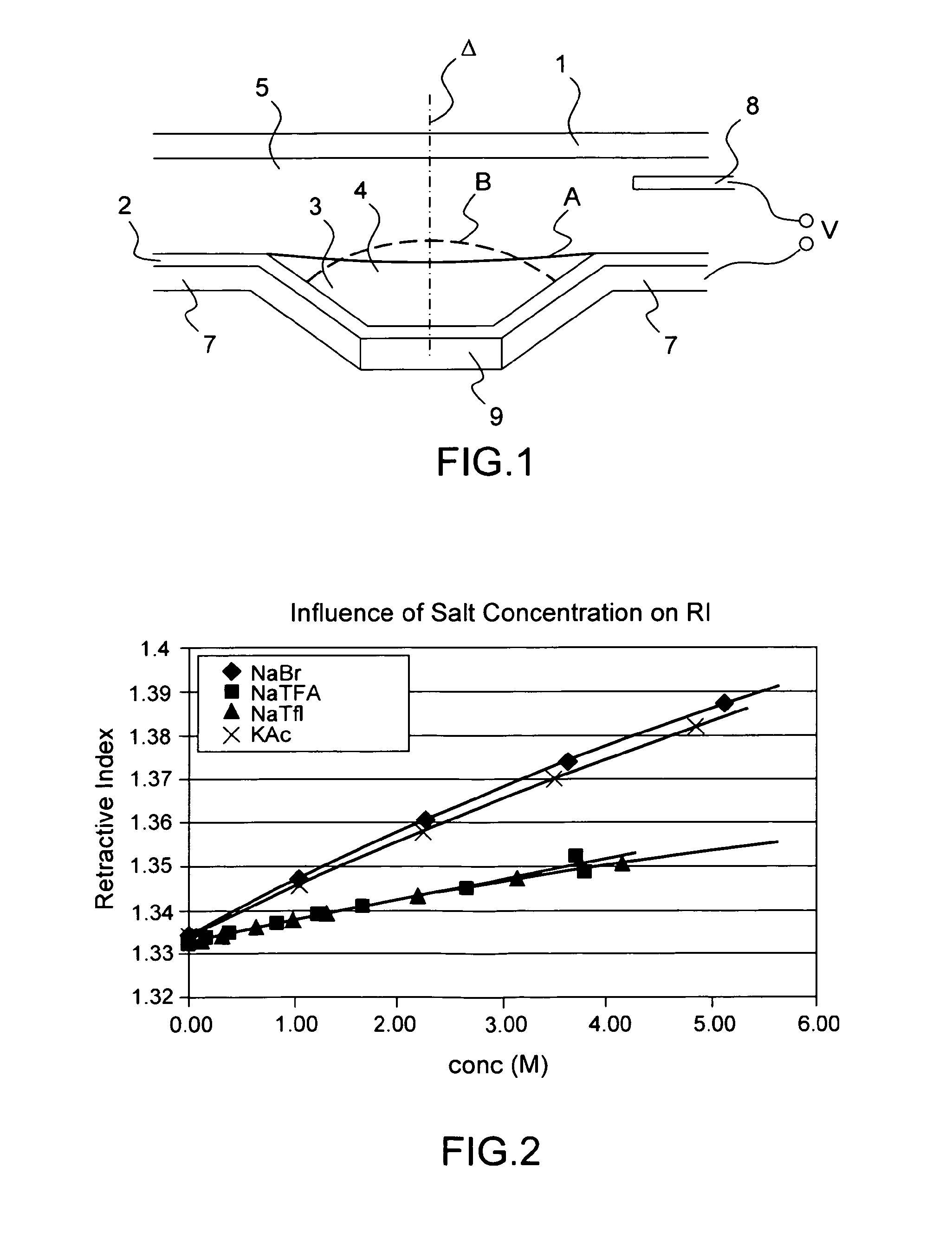
[0086]FIG. 1 shows a simplified cross-section view of an example of a variable focal length liquid lens according to a preferred embodiment. A cell is defined by an insulating plate 1, side walls (not shown) and a dielectric transparent enclosure 2. The cell is filled with a conductive liquid 5. The dielectric enclosure 2 has a low wettability with respect to conductive liquid 5. In the embodiment shown, a lower wall or plate of the dielectric enclosure 2 includes a hollow 3, centered around an axis Δ perpendicular to this plate. In FIG. 1, hollow 3 is a truncated cone. A drop of non-conductive liquid 4 is placed in hollow 3. Liquid drop 4 naturally takes a position A centered on axis Δ. Non-conductive liquid 4 and conductive liquid 5 are both transparent, non-miscible, they have different optical indexes and have substantially the same density. The dioptre formed between liquids 4 and 5 forms a surface of a liquid lens, the optical axis of which is axis Δ and the other surface of w...


PUM


Abstract

An electrowetting optical device is provided comprising a conductive liquid and a non-conductive liquid, the liquids being non miscible, having different refractive indices and forming an interface, wherein the conductive liquid comprises from 5% by weight of a fluorinated salt, based the total weight of the conductive liquid. An apparatus comprising said electrowetting optical device is described as well.

Description

FIELD OF THE INVENTION[0001]The disclosure relates to an electrowetting optical device comprising a multi-phase liquid composition. In particular, the disclosure relates to an electrowetting optical device comprising a conductive liquid and a non-conductive liquid, said liquids being non-miscible having different refractive indices and forming an interface. Preferably, the difference in the refractive index of said liquids is greater than 0.24, preferably over a broad temperature range, preferably from −30° C. to 85° C. Unless otherwise indicated, the expressions “high difference of refractive indices” and “broad temperature range” are intended within this meaning throughout the present description and the following claims.[0002]In the present description and in the following claims, conductivity refers to electrical conductivity.BACKGROUND ART[0003]Optical lens driven by electrowetting and of variable focal length are described in European Patent EP-B1-1,166,157, the content of whi...

Claims


Application Information

Patent Timeline
Patent Type & Authority Applications(United States)
IPC IPC(8): G02B26/00
CPCG02B26/005G02B3/14
Inventor MAILLARD, MATHIEUMALET, GERALDINEOBER, MATTHIAS STEFANDERMODY, DANIEL L.
Owner INVENIOS FRANCE SAS
Why Eureka
Try Eureka