High Current Switching Converter for LED Applications

Active Publication Date: 2013-11-28
ADVANCED ANALOGIC TECHNOLOGIES INCORPORATED
View PDF7 Cites 30 Cited by
  • Summary
  • Abstract
  • Description
  • Claims
  • Application Information

AI Technical Summary

Benefits of technology

[0043]The converters described above are ideally suited to powering one or more LEDs in a camera flash. In such applications, the current provided to the LED's may be efficiently controlled

Problems solved by technology

At higher currents, the input current demand of a charge pump becomes excessive.
Moreover in a camera flash application, the LED conduction duration is limited to a few hundred milliseconds.
If the inductor current drops too low, however, the LED brightness will fall to unacceptable brightness levels.
One major limitation of an inductive boost converter is its need to draw high currents from the battery.
High currents flowing from and through the battery can cause a number of problems including sudden and unwanted voltage transients.
Because the resistance is not negligible, high currents can cause excess heating inside the battery pack and an unwanted voltage drop within the battery pack itself.
If this voltage is too low, it may trigger under-voltage protection in circuitry being powered by the battery, shutting off the electrical load and interrupting the product's operation.
The user perceives the impact of this unwanted voltage transient as spurious or unreliable product operation, or in the very least, as a shortened battery life.
Aside from issues of voltage transients from high currents, the overall power demanded by the LED during a camera fla

Method used


Image

  • High Current Switching Converter for LED Applications
  • High Current Switching Converter for LED Applications
  • High Current Switching Converter for LED Applications

Examples


Embodiment Construction

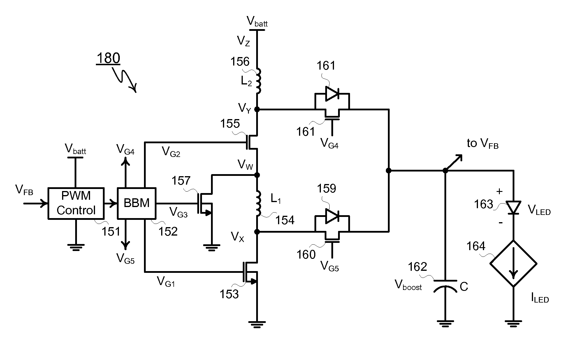
[0064]As shown in FIG. 4, disclosed boost converter 70 comprises PWM controller, break-before-make gate buffer 71, power MOSFETs 73, 75 and 77, inductors 76 and 74, rectifier diodes 78 and 79, and output capacitor 80. Unlike conventional single inductor boost converters, inventive boost converter 70 made in accordance with the present invention comprises two inductors that during magnetizing are connected and series and draw a prescribed amount of current from the battery. When transferring their energy to the converter's output, both inductors are connected to a common node, i.e. the output, thereby delivering twice the input current to the output. In the example shown, the disclosed converter drives a high current load, in this case, flash LED, i.e. light emitting diode, 81. The current ILED in LED 81 is controlled by adjustable current source 81, ranging from zero to the maximum current supplied by boost converter 70.

[0065]Topologically boost converter 70 includes MOSFETs 73 and ...


PUM


Abstract

A step-up switching voltage regulator includes two or more inductors and a switching network. A control circuit drives the switching network in a repeating sequence that includes: a magnetizing phase where the inductors are connected in series between an input voltage and ground; and a charge transfer phase where the inductors are connected in parallel to provide current to an output node with at least one of the inductors is connected between ground and the output node.

Description

BACKGROUND OF THE INVENTION[0001]Many applications exist for step-up voltage converters capable of delivering high-currents. One such application is the need to drive LEDs at high currents for the camera flash function. The brightness of white LEDs is proportional to current. Currents may range from a few hundred milliamperes to several amperes. At high currents the voltage drop across a white LED can be more than three to four volts. Special high-intensity LEDs for high brightness camera flash applications exhibit even higher voltages, voltages higher than the voltage of a single cell lithium ion battery. In order to drive such high brightness LEDs, the battery voltage must be stepped up to a higher potential.[0002]While charge pump converters can be used up to one half ampere, the input current of a charge pump is multiplied by the voltage conversion ratio. A doubler charge pump produces an output voltage double its input but requires an input current at least double its output. S...

Claims


Application Information

Patent Timeline
IPC IPC(8): H02M3/158H05B37/02H05B44/00
CPCH02M3/158H05B37/02H05B45/38H05B47/10
Inventor WILLIAMS, RICHARD
Owner ADVANCED ANALOGIC TECHNOLOGIES INCORPORATED
Why Eureka
Try Eureka