RF coil and magnetic resonance imaging device

a magnetic resonance imaging and coil technology, applied in the field of magnetic resonance imaging (mri), can solve the problems of difficult optimal adjustment of arrangement, insufficient elimination function, image artifacts, etc., and achieve the effect of sufficiently eliminating the magnetic coupling between multi-tuned rf coils and improving image quality

Inactive Publication Date: 2013-11-28
HITACHI LTD
View PDF2 Cites 23 Cited by
  • Summary
  • Abstract
  • Description
  • Claims
  • Application Information

AI Technical Summary

Benefits of technology

[0019]According to the invention, in a multi-element multi-tuned RF coil for an MRI device, magnetic coupling between multi-tuned RF coils is sufficiently eliminated and image quality is improved.

Problems solved by technology

This magnetic coupling causes image artifact and the like.
In the case of the first magnetic coupling elimination method, the degree of freedom of the arrangement of the RF coils is low, and thus it is difficult to optimally adjust the arrangement to balance the elimination of the magnetic coupling with the improvement in receiving sensitivity.
Particularly, the elimination function is not sufficient when strong magnetic coupling is generated between adjacent RF coils.

Method used


Image

  • RF coil and magnetic resonance imaging device
  • RF coil and magnetic resonance imaging device
  • RF coil and magnetic resonance imaging device

Examples


first embodiment

[0039]A first embodiment to which the invention is applied will be described. In this embodiment, a phased array coil in which each coil is a multi-tuned RF coil is used as a receive RF coilreceive RF coil. Hereinafter, in all of the drawings for illustrating embodiments of the invention, parts having the same function will be denoted by the same numerals and their repeated descriptions will be omitted.

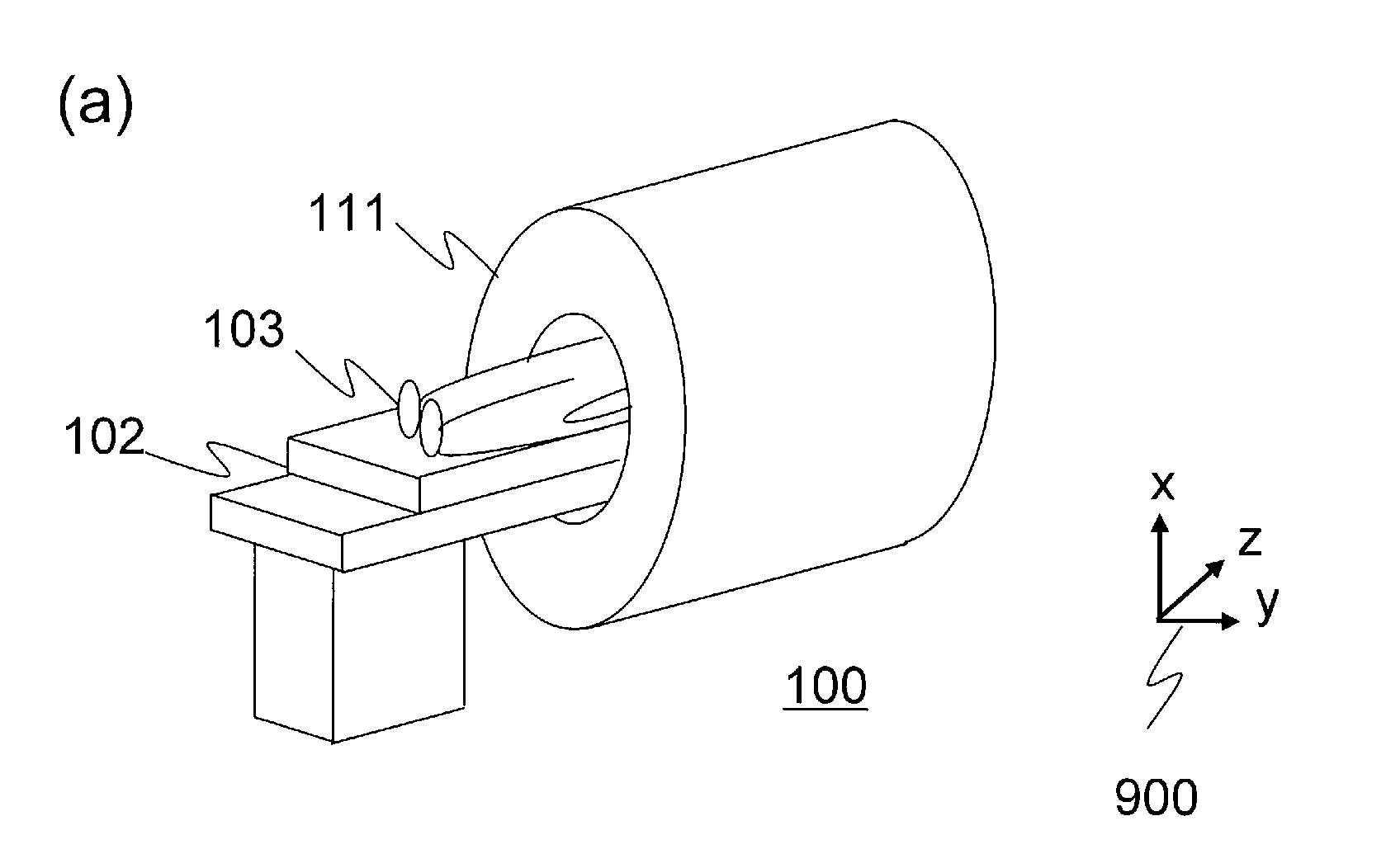
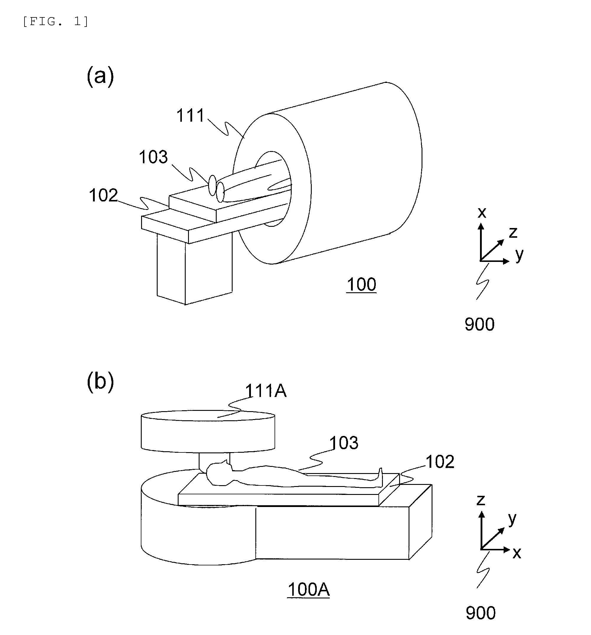
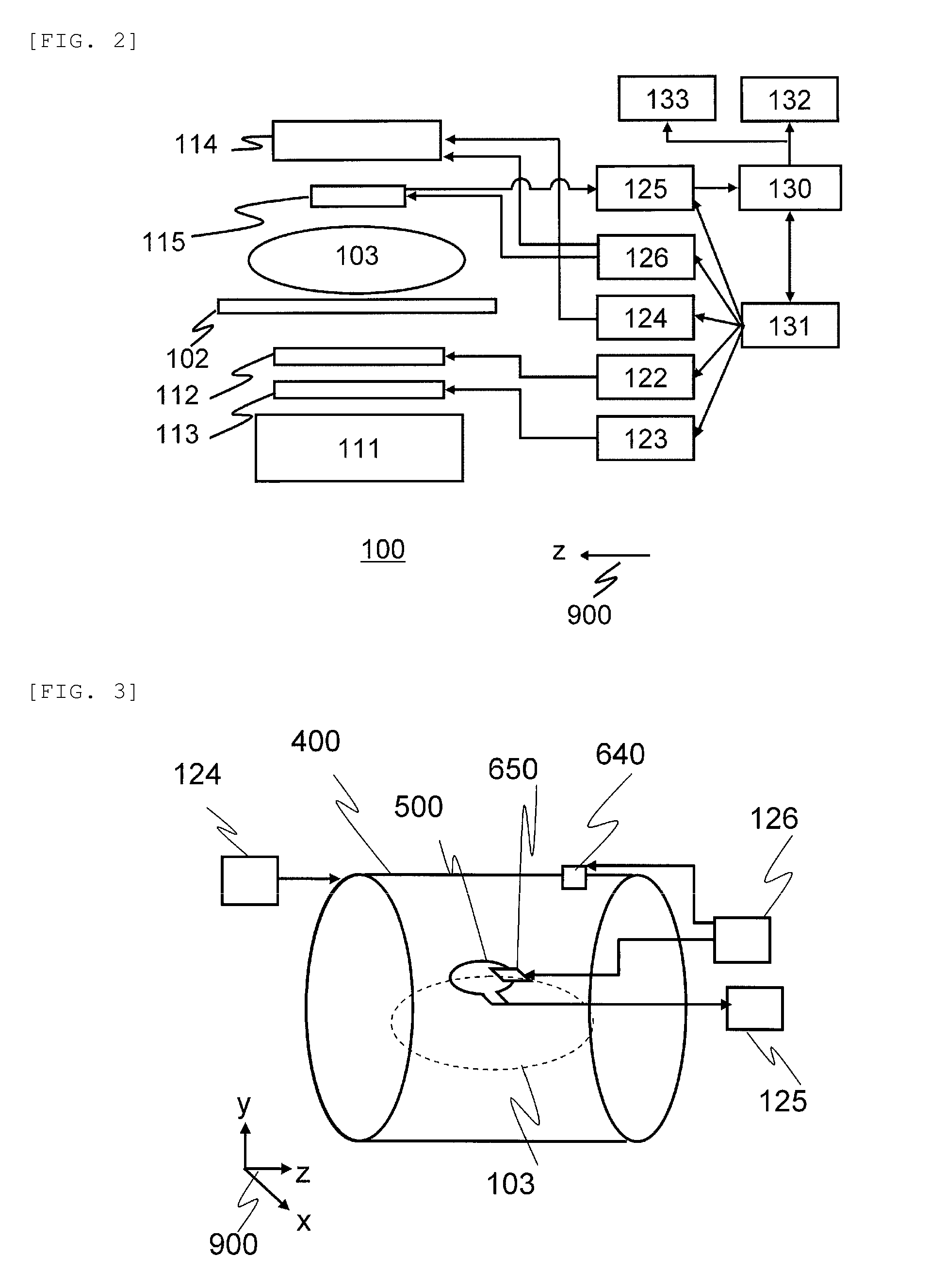
[0040]First, the overall configuration of an MRI device of this embodiment will be described using FIG. 1. FIG. 1 show appearance diagrams of the MRI device of this embodiment. FIG. 1(a) shows a horizontal magnetic field MRI device 100 using a tunnel-type magnet which forms a static magnetic field by a solenoid coil. FIG. 1(b) shows a hamburger-type (open-type) vertical magnetic field MRI device 100A which uses a magnet separated in the vertical direction in order to increase an open feeling. These MRI devices 100 and 100A are provided with a table 102 on which a test object 103 is pl...

examples

[0136]Hereinafter, a double-tuned surface coil 510 of this embodiment will be manufactured by way of trial, and results of evaluation on magnetic coupling elimination performance will be shown. Here, a double-tuned surface coil (invention trial RF coil) having a circuit configuration similar to that of the double-tuned surface coil 510 and a conventional double-tuned surface coil (conventional coil) are prepared to have the same size and outline shape, and compared in terms of high-frequency passing characteristics of a coil part.

[0137]The coil parts of the invention trial RF coil and conventional coil which have been trially manufactured are 80 mm by 60 mm in length and width and have a rectangular shape. The magnitude of the inductance is 210 nH.

[0138]In addition, fluorine and a hydrogen nucleus are set as reception object nuclides of the invention trial RF coil and the conventional coil. That is, both of the coils are prepared to be tuned to both of a nuclear magnetic resonance f...

second embodiment

[0160]Next, a second embodiment to which the invention is applied will be described. An MRI device of this embodiment is basically similar to the first embodiment. However, in this embodiment, a QD coil which has a combination of two double-tuned surface coils 510 of the first embodiment and realizes a QD system is used as a receive RF coilreceive RF coil. Hereinafter, the description will be given, focusing on a configuration different from that of the first embodiment.

[0161]FIG. 17 shows diagrams for illustrating a QD coil 800 which is used as a receive RF coilreceive RF coil 115 of this embodiment. FIG. 17(a) is a diagram for illustrating arrangement and a configuration of the QD coil 800. As shown in FIG. 17(a), the QD coil 800 of this embodiment is provided with a first double-tuned surface coil 810 and a second double-tuned surface coil 820.

[0162]Each of the first double-tuned surface coil 810 and the second double-tuned surface coil 820 has a configuration similar to that of ...


PUM


Abstract

To provide a technique for sufficiently eliminating magnetic coupling between RF coils and improving image quality when a multi-element multi-tuned RF coil is used as a receive RF coil for an MRI device. In the invention, each of RF coils which constitute a multi-element multi-tuned RF coil which is used as a receive RF coil for an MRI device is provided with an inter-coil magnetic coupling prevention circuit which resonates at each frequency to which each RF coil is tuned and provides a high impedance. The inter-coil magnetic coupling prevention circuit adjusts an inductor and a capacitor so that both of a circuit on the side of a pre-amplifier viewed from both ends of a signal reception circuit and a circuit on the side of the signal reception circuit viewed from both ends of a serial resonance circuit connected to the pre-amplifier resonate at a plurality of frequencies to which the respective RF coils are tuned.

Description

TECHNICAL FIELD[0001]The present invention relates to a magnetic resonance imaging (MRI) technique, and particularly, to a radio frequency (RF) coil for use in photographing of a nuclear magnetic resonance image of a plurality of nuclides.BACKGROUND ART[0002]MRI devices are diagnostic imaging devices for medical use which obtain, from a magnetic resonance signal that is generated by making atomic nuclei in an arbitrary cross-section across a test object cause magnetic resonance, a cross-sectional image in the cross-section. Generally, in MRIs, a magnetic resonance signal which is generated from a hydrogen nucleus (1H) is a measurement object. However, the MRIs can also measure nuclear magnetic resonance signals of many nuclides such as fluorine (19F), phosphorus (31P), sodium (23Na), and carbon (13C).[0003]For example, in order to simultaneously obtain images that are formed from nuclear magnetic resonance signals of a plurality of kinds of different atomic nuclei, it is necessary t...

Claims


Application Information

Patent Timeline
Patent Type & Authority Applications(United States)
IPC IPC(8): G01R33/36
CPCG01R33/365G01R33/34053G01R33/34069G01R33/34076G01R33/422G01R33/3635G01R33/3657G01R33/3678G01R33/3415
Inventor OTAKE, YOSUKESOUTOME, YOSHIHISASATO, RYOTABITO, YOSHITAKAHIRATA, KOJI
Owner HITACHI LTD
Why Eureka
Try Eureka