In-situ Forming foams with outer layer

a foam and outer layer technology, applied in the field of polymer foams, can solve the problems of limiting efficacy, morbidity or mortality, internal bleeding which is often fatal, etc., and achieves the effects of promoting material cohesion, resisting deformation and movement, and hardening more slowly

Active Publication Date: 2013-11-28
ARSENAL MEDICAL
View PDF1 Cites 24 Cited by
  • Summary
  • Abstract
  • Description
  • Claims
  • Application Information

AI Technical Summary

Benefits of technology

[0027]The polymer foams of the present invention are formed “in-situ.” That is, the foams are formed by the reaction of polymer(s) in-situ simultaneously with, or shortly after, delivery to an aneurysm, sac or other bodily cavity. It should be understood that, throughout the description of the present invention, the systems and methods of the present invention are applicable to any suitable bodily cavity notwithstanding that the invention is described with specific reference to the treatment of aneurysms. The polymer(s) react in the presence of an aqueous environment (e.g., blood, water, etc,) or other trigger (e.g., pH, temperature, ion concentration, electrical current, magnetic field or other trigger) in a one-part system and / or react with each other (e.g., for embodiments in which polymer components are delivered separately and either concurrently or sequentially) in a two- or multi-part system, upon such delivery. This is in contrast to pre-formed foams, which are formed prior to the time that they are delivered into the body. The foamed polymers of the present invention, may be capable of exerting a pressure on an internal surface of an aneurysm sac and thus prevent or limit movement of a bodily fluid (e.g., blood, etc.) and / or prevent or limit endoleaks as previously described. Such in-situ forming foams preferably expand to fill the aneurysm sac volume, resulting in conformal contact with the aneurysm walls and may include penetration into blood vessels and other lumens opening into the sac without clinically undesirable embolization. The location of such vessels is not always obvious with standard imaging technique, such that the ability to seal such vessels with the foams and methods of the present invention without requiring visualization is a unique advantage of the present invention. Also, the foams are formed by the reaction of polymers in-situ to yield gas generation and expansion, which allow for the use of minimal polymer materials to fill the space and allows the resulting foam to push through fluid, including actively flowing blood, to provide conformal contact with surrounding tissue.
[0028]In some embodiments, the foam of the present invention is described to be “lava like” in that it is viscous yet flowable and hardens from its exterior surface towards its interior. The external skin of the foam forms as a fast-forming, robust, balloon-like outer layer that encases the polymer formulation, promotes material cohesion, and resists deformation and movement into collateral vessels or outside the targeted area. Formation of the skin occurs in whole or in part due to contact with a trigger in the environment (e.g., water, temperature, blood, etc.), and therefore, as the foam expands and the skin deforms to expose internal formulation, it too will react and reform the skin rapidly. The outer layer may be characterized as being “robust” because it has mechanical properties (e.g., strength, toughness, etc.) that are more optimal, at least for some period of time, to the material contained by the skin. The interior of the material hardens more slowly via the same or a secondary process, as compared to the skin. In some cases where the skin forms rapidly and is likely sufficiently robust mechanically, resulting in a continuous, packable polymer, which may tend to form as a coil. Through continued extrusion of the material out of a delivery device such as a catheter or microcatheter, the user can create a long coil to partially or completely fill an aneurysm space or other bodily cavity. The space may be filled with an aneurysm coil or other medical device and an in-situ forming foam or an aneurysm coil or other medical device that is coated with a material that expands to form a foam coating in-situ. The continuous, long aspect ratio of the coil and cured outer surface prevents the coil from entering the collateral vessels to a significant degree, which could lead to adverse events. In addition, some embodiments could be envisioned where the coil diameter expands to a size that is larger than any of the collateral vessel diameters, thus preventing entry into the collateral vessels in the short aspect ratio as well. These and other factors are important distinctions and advantages of in-situ forming foams over systems and methods that make use of pre-formed foams.
[0029]The polymer foams of the present invention may possess attributes that make them particularly suitable for use within the body. For example, the foams of the present invention are biocompatible and may be either biodegradable or biostable. In some instances, the polymers may be sufficiently elastic to allow for body movement while being sufficiently stiff to support body tissues and the endovascular graft or associated or similar medical devices. In some embodiments, the composition may be adjusted so that it wets tissues effectively. Furthermore, pendant groups may be attached that allow for the targeted adhesion of polymer to tissues or injured tissues. Functionalization of the polymer used to form the foam may also lead to covalent bonding of the foam to a surface inside the aneurysm sac, which may aid, for example, in preventing dislocation of the foam within the cavity. In addition, the polymers may comprise entities that allow for the degradation of the polymer foam via an external stimulus such as UV radiation, heat, etc. The polymers and / or foams formed therefrom may also be capable of interacting with contrast agents, allowing for the visualization of the foam and / or an aneurysm sac. This interaction may be permanent or temporary. These and other aspects of the foams used in the present invention are more fully described herein.
[0030]Examples of in-situ forming foams and methods of using such foams for the treatment of aneurysms are now provided.
[0031]FIG. 1 shows the placement of a stent-graft within an abdominal aortic aneurysm, as is known in the art. Although the present invention is described with specific references to the treatment of AAAs, it should be appreciated that it is applicable to the treatment of any aneurysm, such as those in the descending thoracic aorta, in the peripheral vasculature, and in the brain. Any graft, stent-graft, balloon, or the like insertable into an aneurysm sac or other bodily cavity is suitable for use in the current invention as the insertable medical device, such as the ANEURX AAADVANTAGE®, TALENT®, and ENDURANT® stent-grafts manufactured by Medtronic, Inc. Such stent-grafts typically include a metallic scaffold supporting a synthetic material, such as a woven or unwoven mesh or fabric that is placed over, within or around the scaffold. The stent-graft expands into place after being delivered through an EVAR procedure, as is known in the art. Although the stent-graft shown in FIG. 1 is a so-called “branched” or “bifurcated” stent-graft because it branches into legs 151, 152, it should be recognized that unbranched stent-grafts (i.e., stent-grafts that are bifurcated into legs) are suitable for use in the present invention. Also suitable for use in the present invention are fenestrated stent-grafts, or chimney or snorkel grafts as are known in the art.
[0032]Regardless of whether a branched or unbranched stent-graft is used, the stent-graft will include a first end 160, second end 161 and / or 162, and a lumen 170 extending there between. The first end 160 of stent-graft 150 is secured to a first end 111 of aneurysm 110. As used herein, a graft or stent-graft is said to be “secured” to the end of an aneurysm if it is held into contact with surrounding tissue, such as by friction fit without the use of any securing means or alternatively with the use of such securing means such as barbs, staples, sutures, adhesives, or other suitable securing means. The second end 161 and / or 162 of stent-graft 150 is secured to a second end 112 of aneurysm 110 to span the aneurysm and form a stable channel for blood flow within abdominal aorta 115.

Problems solved by technology

However, it can be appreciated that movement of that material outside the targeted treatment zone could have undesirable effects, cause complications, limit efficacy or lead to morbidity or mortality.
If left untreated, aneurysms can grow large and rupture, causing internal bleeding which is often fatal.
Such endoleaks represent a significant possible drawback to EVAR procedures as they could lead to aneurysm expansion or rupture.
Endoleaks are less of a concern following surgical repair of AAA, but the surgical procedure is significantly more invasive and has higher mortality and morbidity.
Such a pre-formed foam, however, cannot be shaped in-situ to conform to the configuration of the aneurysm sac.

Method used


Image

  • In-situ Forming foams with outer layer
  • In-situ Forming foams with outer layer
  • In-situ Forming foams with outer layer

Examples


example 1

[0109]A plastic cap was used to simulate an aneurysm with two 4 mm ID lumbar arteries (bottom) and one 6 mm ID IMA (top). Additionally, the model was operated under a static bead of fluid pressure such that a flow rate of 40 ml / min out of the IMA and into the lumbar arteries was maintained. The material was delivered in <5 minutes to fill the 40 ml aneurysm via a 1.8 mm ID blunt tip.

[0110]During and after the delivery the material remained cohesive and remained in the target location, without embolizing the model collateral vessels. Within minutes after delivery was completed the material solidified in the interior and foamed forming a robust elastic foam.

example 2

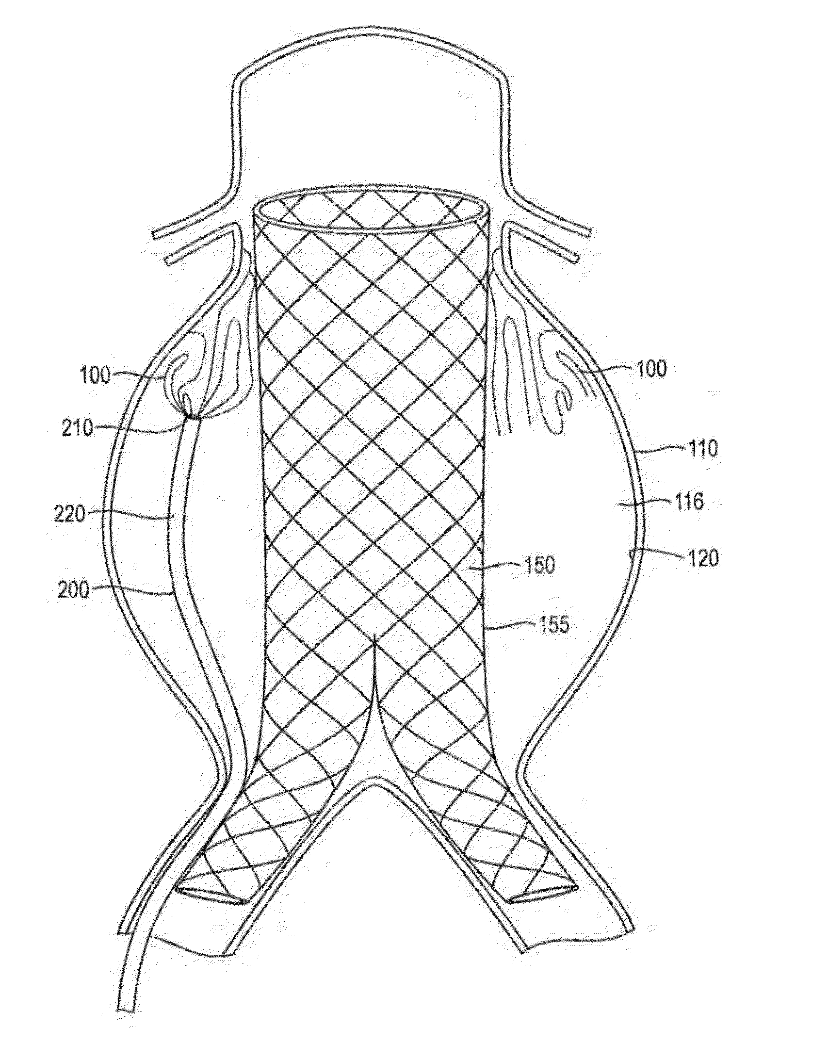
[0111]In this example, a in-situ forming foam demonstrated beneficial performance in an anatomically correct model. An anatomically correct model of a large human aortic aneurysm was made of molded silicone. The model had an aneurysm volume of 285 ml and a complex geometry. A bifurcated sent graft (36×20 mm) with a 16 mm extension was deployed in the model prior to injection of the material into the space between the grab and the aneurysm wall The formulation delivered via a 4 mm catheter effectively filled 90% of the space between the graft and the model without compromising the proximal or distal seal zones. The skin of the formulation impinged upon the graft but did not affect the diameter of the stent graft lumens and stayed within the aneurysm space without migrating into the collateral vessels. The formulation formed an elastic foam within minutes after deployment. This example demonstrates the benefits of lava-like foam characteristics in effectively and selectively filling a...

example 3

[0112]In this example, an isocyanate prepolymer formulation was coated with a siloxane based formulation and delivered through a coaxial delivery catheter. The two streams were not coaxial, but were attached to each other and delivered in parallel.


PUM

PropertyMeasurementUnit
bulk modulusaaaaaaaaaa
pore sizeaaaaaaaaaa

Abstract

Systems, methods and kits relating to in-situ forming polymer foams for the treatment of aneurysms or fluid filled spaces are disclosed. The systems include an insertable medical device and an in-situ forming foam of lava like materials with a fast forming outer skin and a slower hardening interior that is formed from a one-, two- or multi-part formulation. When used to treat an aneurysm, the foam is placed into contact with at least a portion of an exterior surface of the medical device and / or the tissue surface of the aneurysm.

Description

CROSS-REFERENCE TO RELATED APPLICATIONS[0001]This application is a continuation-in-part of U.S. application Ser. No. 13 / 209,020, filed Aug. 12, 2011 and titled “In-situ Forming Hemostatic Foam Implants,” which is a continuation-in-part of U.S. application Ser. No. 12 / 862,362, filed Aug. 24, 2010 and titled “Systems and Methods Relating to Polymer Foams,” which claims priority to U.S. Provisional Patent Application Ser. No. 61 / 236,314 filed Aug. 24, 2009, titled “Systems and Methods Relating to Polymer Foams,” each of which is incorporated by reference herein for all purposes.FIELD Of INVENTION[0002]Systems and methods relating to polymer foams for the treatment of aneurysms and other body cavities are generally described.BACKGROUND[0003]Controlling fluid, gas or material movement in the body has numerous clinical applications and benefits, including controlling hemorrhage, preventing aneurysm growth or risk of rupture, treating tumors and managing respiratory disorders. These treatm...

Claims


Application Information

Patent Timeline
Patent Type & Authority Applications(United States)
IPC IPC(8): A61M37/00
CPCA61M37/00A61L31/06A61J1/2093A61L31/128A61L31/146A61L24/0036A61L24/0089A61L24/046A61L2400/06A61F2/07A61F2002/065A61F2002/077A61F2210/0085A61B17/12113A61B17/12118A61B17/1214A61B2017/1205C08L83/04C08L67/04A61B17/12181A61L2300/60
Inventor FREYMAN, TOBYLOMAKIN, JOSEPHMARINI, JOHNMORTENSEN, JENNIFERRAGO, ADAMBUSOLD, RANYSHARMA, UPMAZUGATES, GREGORY T.
Owner ARSENAL MEDICAL
Why Eureka
Try Eureka