Medical device ameneable to fenestration

a technology of medical devices and fenestration, applied in the field of medical devices, can solve the problems of high morbidity and mortality rates, inapplicability of technology, and insufficient proximal vessel length to achieve adequate fixation

Inactive Publication Date: 2013-11-28
WL GORE & ASSOC INC
View PDF7 Cites 0 Cited by
  • Summary
  • Abstract
  • Description
  • Claims
  • Application Information

AI Technical Summary

Benefits of technology

[0020]In one surgical method, an implantable medical device utilizing the present invention is placed at a surgical site with conventional or interventional surgical techniques. Once the correct position of the medical device is confirmed, a catheter guide-wire, or other surgical instrument, is used to breach the breachable barrier material and begin to uncover the covered opening. An expandable balloon catheter in a deflated configuration is then inserted into the partially uncovered opening and inflated....

Problems solved by technology

Left untreated, these aneurysms commonly progress to rupture resulting in death.
Due to the often emergent condition of these patients and the potential for significant blood loss, high morbidity and mortality rates have been associated with this type of surgery.
Despite these improvements, there are many patients for which this technology is not applicable as a result of unique anatomical or disease conditions.
In many patients, the proximal vessel is not long enough to achieve adequate fixation.
Widespread applicability of supra-renal fixation devices has been limited by the flexibility of these designs, morphological variation of aneurysmal neck geometry across patients, and the coverage of the renal ostia with metallic stents which can act as a nidus for thromo-embolism of the renal circulation and/or hinder subsequent interventional access to this vasculature....

Method used


Image

  • Medical device ameneable to fenestration
  • Medical device ameneable to fenestration
  • Medical device ameneable to fenestration

Examples


example 1

[0072]A planar sheet embodiment of the present invention, approximately 8.3 cm (3.25″) by 13.3 cm (5.25″), was constructed as follows. A first layer of an expanded polytetrafluoroethylene (ePTFE) sheet material having a thickness of about 0.4 mm was obtained from the Medical Products Division of W.L. Gore & Associates, Inc., Flagstaff, Ariz. under the tradename GORE-TEX® Cardiovascular Patch as part number 1800610004 (FIG. 12, part A1).

[0073]A second layer of a fluoro-elastomeric sheet material composed of a thermoplastic copolymer of tetrafluoroethylene (TFE) and perfluoro(methyl vinyl ether) (PMVE) was constructed by compression molding the crumb form of the copolymer at a temperature of about 250° C. to form a sheet about 0.2 mm (0.008″) in thickness (FIG. 12, part A3). The resulting material had the attributes described in TABLE 1 below.

[0074]A third layer of sheet material (FIG. 12, part A4) is composed of ePTFE made according to U.S. Pat. No. 4,482,516, issued to Gore. The she...

example 2

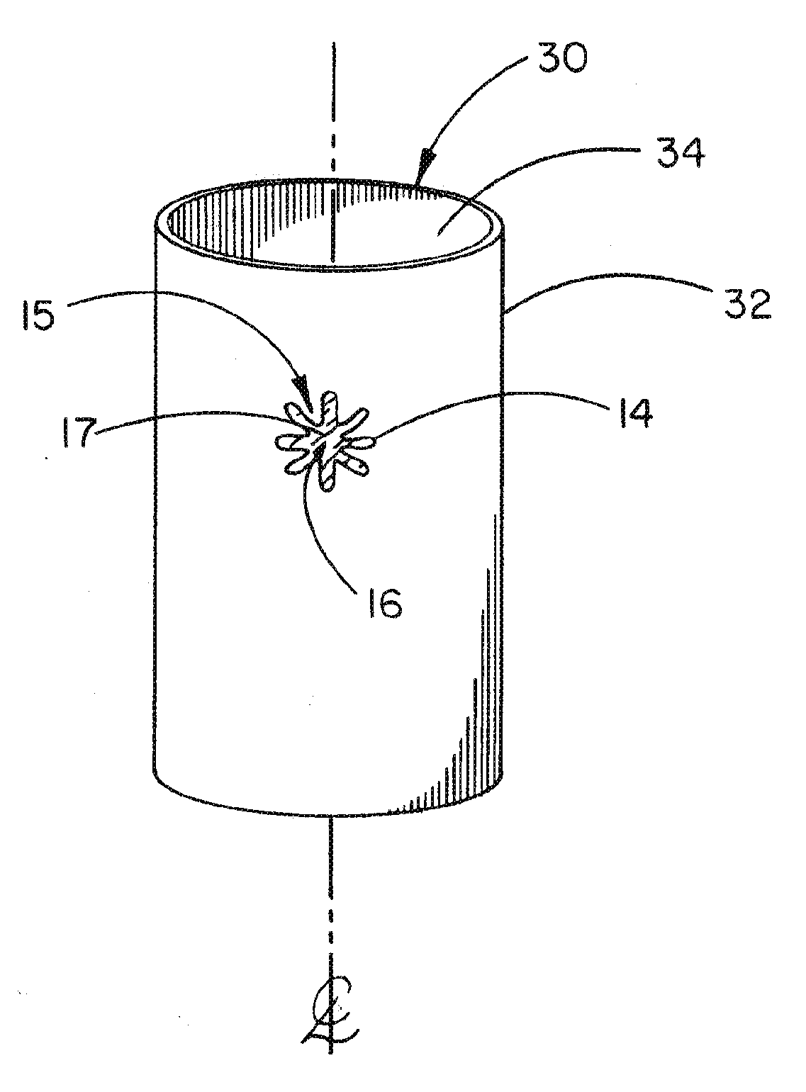
[0078]This example describes a tubular vascular graft having the article of Example 1 incorporated into the wall of the tubular graft. The article of Example 1 was trimmed and sewn into a corresponding hole cut through the wall of an ePTFE vascular graft. The ePTFE vascular graft was a GORE-TEX® Vascular Graft available from the Medical Products Division of W.L. Gore & Associates, Inc., Flagstaff, Ariz. as part number SA1604. The article from Example 1 was sewn into the corresponding hole of the tubular construct with an ePTFE suture material obtained from Medical Products Division of W.L. Gore & Associates, Inc. Flagstaff, Ariz. under the tradename GORE-TEX® Suture as part number CV-5. The resulting article is shown in FIG. 3B.

[0079]Accurate and illustrative examples of the invention have been described in detail however, it is readily foreseen that numerous modifications may be made to these examples


PUM


Abstract

The present invention is directed to a device that permits a permanent aperture to be formed in a wall, or other partition, of an implantable medical device. The present invention maintains the continuity and fluid-retaining properties of the implantable medical device by providing a breachable barrier material fully covering an opening delimited by a deformable framework. The invention is accessed with conventional interventional surgical instruments that disrupt and displace the barrier material. Following disruption of the barrier material, the opening is enlarged with surgical instruments to form a permanent framed aperture in the wall of the implantable medical device. The permanent framed aperture provides fluid communication across the wall of the implantable medical device.

Description

CROSS-REFERENCE TO RELATED APPLICATIONS[0001]This application is a continuation of co-pending U.S. patent application Ser. No. 10 / 251,031, entitled “Medical Device Amenable To Fenestration”, the content of which is hereby incorporated by reference in its entirety.FIELD OF THE INVENTION[0002]The present invention relates to implantable medical devices. More particularly, the invention relates to means for forming a framed aperture in wall portions, or other partitions, of implantable medical devices to establish and maintain fluid communication across the wall portion of the medical device. The present invention also relates to methods of making the invention.BACKGROUND OF THE INVENTION[0003]Abdominal aortic aneurysms (AAAs) and thoracic aortic aneurysms (TAAs) are diagnosed in approximately 250,000 and 20,000 patients respectively each year. Left untreated, these aneurysms commonly progress to rupture resulting in death. Prior to the advent of interventional catheter-based technique...

Claims


Application Information

Patent Timeline
IPC IPC(8): A61L27/50A61F2/06A61F2/82
CPCA61L27/507A61B17/3478A61F2/07A61F2002/061A61F2002/065A61F2002/072A61F2002/075A61F2002/821A61F2/89A61F2220/005A61F2220/0058A61F2220/0075
Inventor CULLY, EDWARD H.CUTRIGHT, WARREN J.NORDHAUSEN, CRAIG T.VONESH, MICHAEL J.WALTER, JAMES T.
Owner WL GORE & ASSOC INC
Why Eureka
Try Eureka