Soot sensor functional capability monitoring

a technology of functional capability and soot sensor, which is applied in the field of soot sensing, can solve the problems of high probability and achieve the effect of fast detection of soot sensor malfunction

Inactive Publication Date: 2013-12-05
DELPHI INT OPERATIONS LUXEMBOURG S A R L
View PDF3 Cites 17 Cited by
  • Summary
  • Abstract
  • Description
  • Claims
  • Application Information

AI Technical Summary

Benefits of technology

[0008]It is an object of the present invention to allow for faster detection of soot sensor malfunct

Problems solved by technology

If the fingerprint of condensing water is absent from the measurement signal when it is expected (i.e. when the physical

Method used


Image

  • Soot sensor functional capability monitoring
  • Soot sensor functional capability monitoring
  • Soot sensor functional capability monitoring

Examples


Embodiment Construction

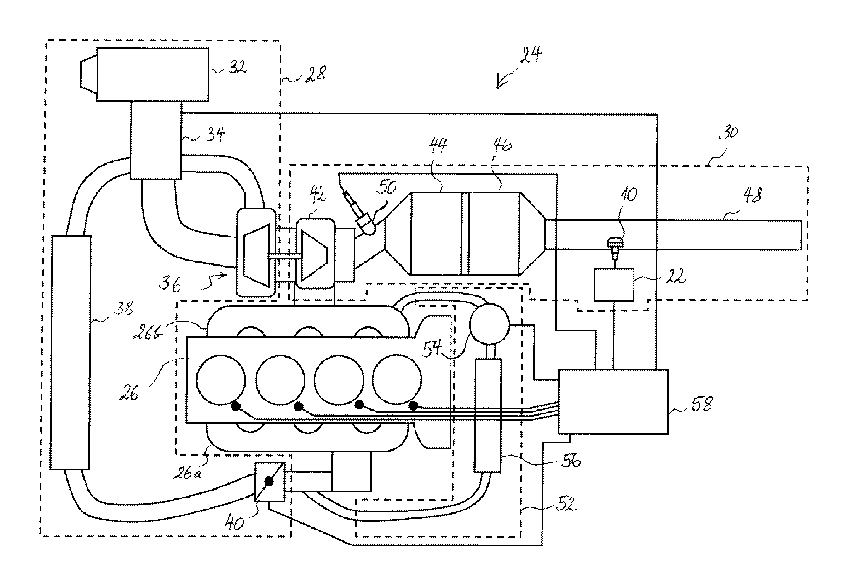
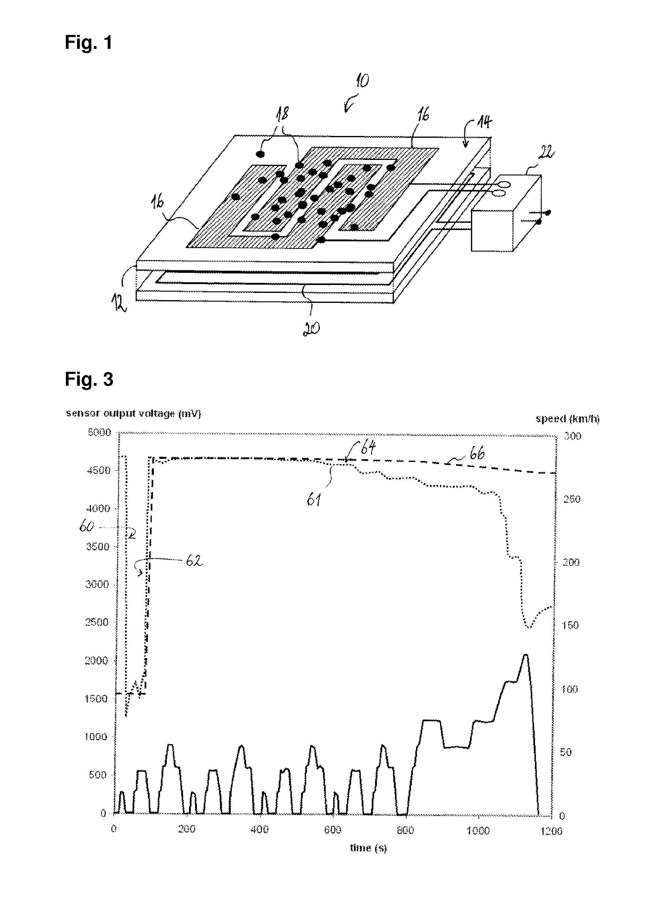
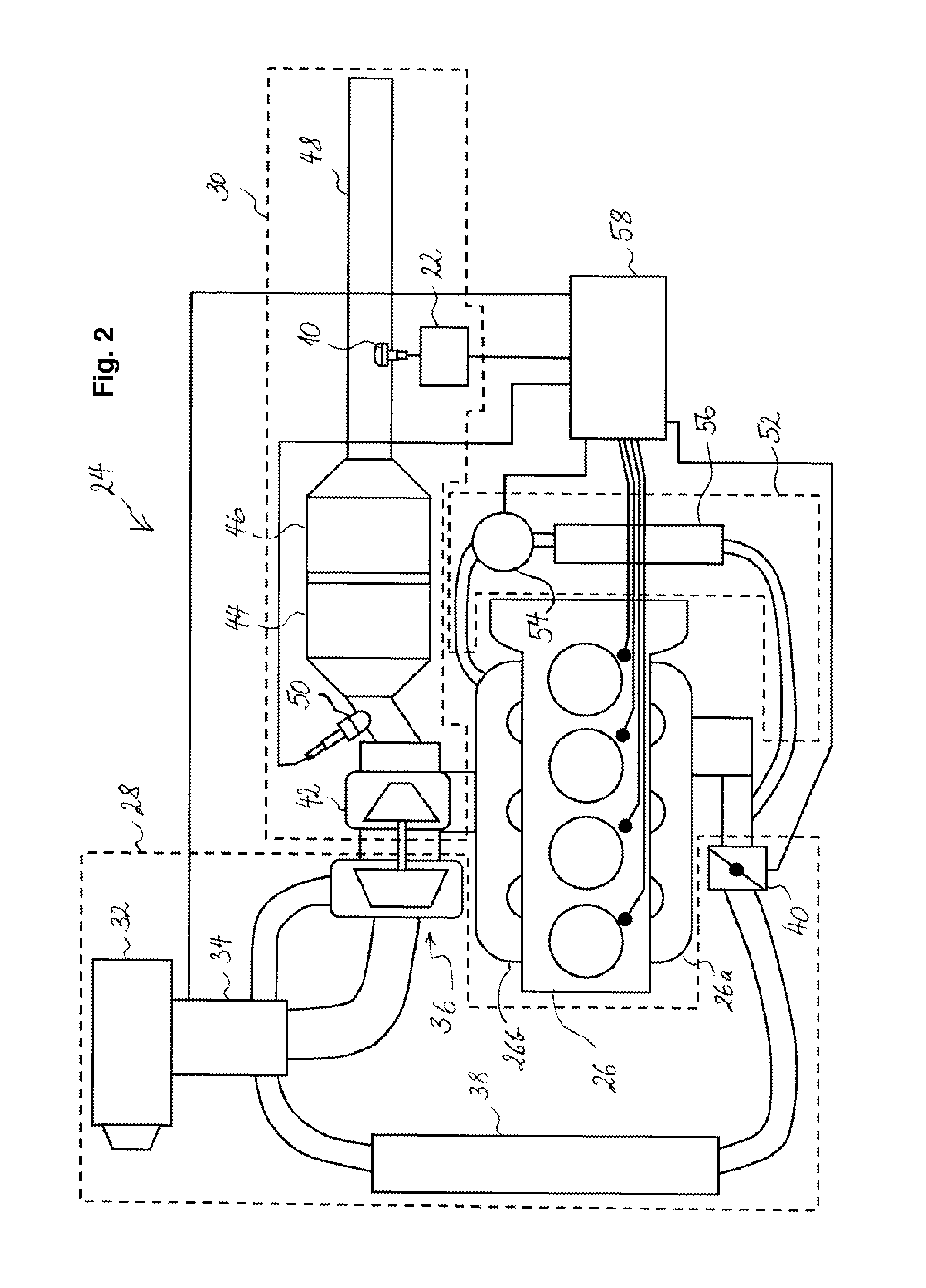
[0027]FIG. 1 shows an example of a soot sensor 10 that works according to a known principle (see e.g. US 2011 / 0015824 for reference). The soot sensor 10 comprises an insulating substrate 12 (e.g. made from ceramic) forming a sensor surface 14 exposed to the exhaust gas. Measurement electrodes 16 are arranged separate from each other on the sensor surface 14 in an interdigitated configuration. As long as the sensor surface 14 is free of soot particles, the electrodes 16 are electrically insulated from each other. When soot particles 18 deposit on the sensor surface 14, they eventually bridge the gap between the electrodes 16, allowing a current to flow between the electrodes 16 in response to a voltage applied between the electrodes 16. The more soot particles deposit on the sensor surface 14, the more conductive channels form between the electrodes 16 and the higher is the current measured. The soot sensor comprises a heating element 20 arranged in heat-conducting contact with the s...


PUM


Abstract

A method of monitoring functional capability of a soot sensor that is responsive to deposition of soot from an exhaust gas stream on a sensor surface comprises acquiring a measurement signal of the soot sensor and running a plausibility check, in which it is ascertained whether the measurement signal agrees with an expected finding. According to the invention it is detected whether conditions are present, on which liquid, e.g. water, from the exhaust gas stream condensates on the sensor surface. Additionally or alternatively, such conditions are produced. The plausibility check then includes ascertaining whether the measurement signal reflects the condensation of liquid. The detection of presence of conditions for condensation comprises a measurement or an estimation of temperature on the sensor surface.

Description

CROSS REFERENCE TO RELATED APPLICATIONS[0001]This application is a national stage application under 35 U.S.C. 371 of PCT Application No. PCT / EP2012 / 052742 having an international filing date of 17 Feb. 2012, which designated the United States, which PCT application claimed the benefit of European Patent Application No. 11155332.7 filed 22 Feb. 2011, the entire disclosure of each of which are hereby incorporated herein by reference.TECHNICAL FIELD[0002]The present invention generally relates to the field of soot sensing, in particular to monitoring the functional capability of a soot sensor.BACKGROUND ART[0003]It is currently possible to meet the requirements of the EU5 and US MY 2010-2012 emission regulations using a differential pressure sensor (also known as a “Delta P sensor”). Such a sensor can detect efficiency and / or malfunctioning of particulate filter by measuring the pressure in the exhaust stream. If the particulate filter is damaged, e.g. it is cracked, the actual pressur...

Claims


Application Information

Patent Timeline
IPC IPC(8): F01N11/00G01M15/10
CPCF01N11/00G01M15/102F02D41/064F02D41/1466F02D41/222G01N15/0656Y02T10/40
Inventor VAN MARION, WILLEM
Owner DELPHI INT OPERATIONS LUXEMBOURG S A R L
Why Eureka
Try Eureka