Negative electrode for power storage device and power storage device

Active Publication Date: 2013-12-05
SEMICON ENERGY LAB CO LTD
View PDF1 Cites 40 Cited by
  • Summary
  • Abstract
  • Description
  • Claims
  • Application Information

AI Technical Summary

Benefits of technology

[0032]In one embodiment of the present invention, the film is provided on a surface of the inorganic compound film provided on part of the surface of the negative electrode active material and on the exposed portion of the negative electrode active material; thus, adhesion between the inorganic compound film and the film can be increased. As a result, separation of the film provided on the exposed portion of the negative electrode active material and the surface of the inorganic compound film due to repeated charge and discharge can be suppressed.
[0033]Further, the inorganic compound film is thinned so that carrier ions can pass through the inorganic compound film and the film is provided in contact with the exposed portion of the negative electrode active material and the inorganic compound film, which makes it possible to suppress the electron conductivity of the inorganic compound film and the film while the carrier ion conductivity of the inorganic compound film and the film is secured. In other words, it is possible to minimize the reductive decomposition reaction of the electrolyte solution on the surface of the negative electrode active material; consequently, a decrease in the capacity of the p

Problems solved by technology

A passivating film of a conventional negative electrode has been considered to be formed due to a battery reaction at the tim

Method used


Image

  • Negative electrode for power storage device and power storage device
  • Negative electrode for power storage device and power storage device
  • Negative electrode for power storage device and power storage device

Examples


embodiment 1

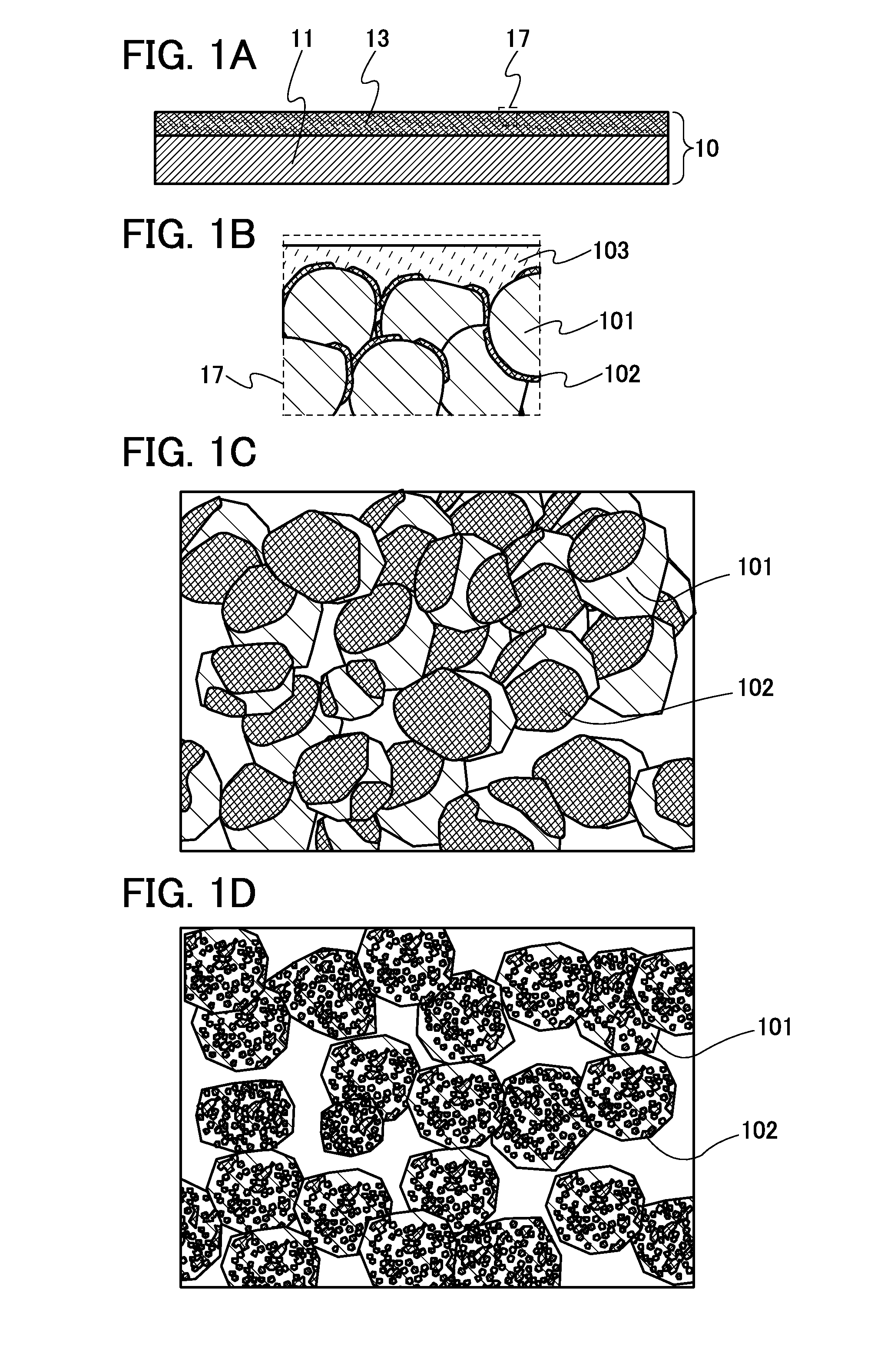
[0058]In this embodiment, a structure of a negative electrode active material having an inorganic compound film which can suppress a decomposition reaction of an electrolyte solution is described with reference to FIGS. 1A to 1D.

[0059]FIGS. 1A and 1B illustrate a negative electrode for a power storage device of the present invention. FIGS. 1C and 1D each illustrate a negative electrode active material used in the negative electrode for a power storage device.

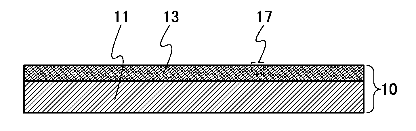
[0060]FIG. 1A is a cross-sectional view of a negative electrode 10 including a negative electrode current collector 11 and a negative electrode active material layer 13 provided on one or both surfaces (on one surface in FIG. 1A) of the negative electrode current collector 11.

[0061]FIG. 1B is an enlarged cross-sectional view of part of the negative electrode active material layer 13 surrounded by the dashed line 17 in FIG. 1A. The negative electrode active material layer 13 includes a negative electrode active material 101 havin...

embodiment 2

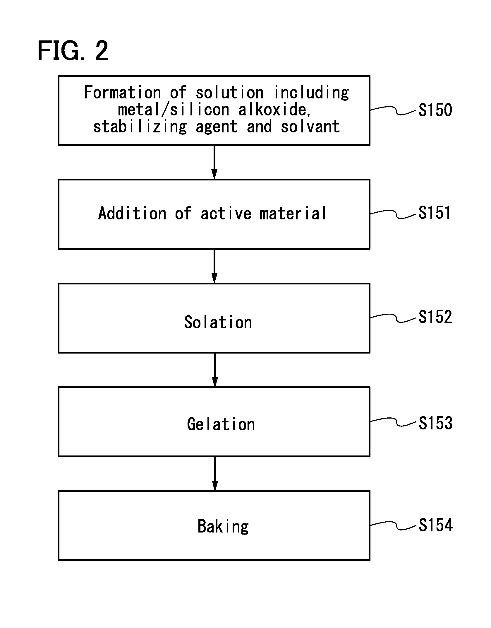
[0084]In this embodiment, a method for forming a particulate negative electrode active material having an inorganic compound film on part of its surface is described with reference to FIG. 2.

[0085]First, as Step S150, a solvent to which metal alkoxide and a stabilizing agent are added is stirred to form a solution. Toluene can be used as the solvent, for example. Ethyl acetoacetate can be used as the stabilizing agent, for example. Alternatively, as Step S150, a solvent to which silicon alkoxide and a stabilizing agent are added is stirred to form a solution.

[0086]For the metal alkoxide, a desired metal used to form the inorganic compound film provided on part of the surface of the negative electrode active material is selected.

[0087]Next, as Step S151, the solution to which a particulate negative electrode active material such as graphite is added is stirred. The solution is made into thick paste by stirring the solution to which a solvent such as toluene is added, and the metal al...

embodiment 3

[0096]In this embodiment, a power storage device including the negative electrode described in Embodiment 1 and a method for forming the power storage device including the negative electrode are described with reference to FIGS. 3A to 3D, FIGS. 4A to 4C, FIG. 5A and 5B, FIG. 6, and FIGS. 7A and 7B.

[0097]First, a negative electrode for a power storage device using a particulate negative electrode active material having an inorganic compound film on part of its surface and a method for forming the negative electrode are described with reference to FIGS. 3A to 3D.

[0098]As illustrated in FIG. 3A, a negative electrode 200 includes a negative electrode current collector 201 and a negative electrode active material layer 202 provided on one or both surfaces (on the both surfaces in the drawing) of the negative electrode current collector 201.

[0099]The negative electrode current collector 201 is formed using a highly conductive material which is not alloyed with a carrier ion such as lithiu...


PUM

PropertyMeasurementUnit
Thicknessaaaaaaaaaa
Thicknessaaaaaaaaaa

Abstract

A decomposition reaction of an electrolyte solution and the like caused as a side reaction of charge and discharge is minimized in repeated charge and discharge of a lithium ion battery or a lithium ion capacitor, and thus the lithium ion battery or the lithium ion capacitor can have long-term cycle performance. A negative electrode for a power storage device includes a negative electrode current collector and a negative electrode active material layer which includes a plurality of particles of a negative electrode active material. Each of the particles of the negative electrode active material has an inorganic compound film containing a first inorganic compound on part of its surface. The negative electrode active material layer has a film in contact with an exposed part of the negative electrode active material and part of the inorganic compound film. The film contains an organic compound and a second inorganic compound.

Description

BACKGROUND OF THE INVENTION[0001]1. Field of the Invention[0002]The present invention relates to a negative electrode for a power storage device and a power storage device.[0003]2. Description of the Related Art[0004]A variety of power storage devices, for example, non-aqueous secondary batteries such as lithium ion batteries (LIBs), lithium ion capacitors (LICs), and air cells have been actively developed in recent years. In particular, demand for lithium ion batteries with high output and high energy density has rapidly grown with the development of the semiconductor industry, as in the cases of electronic appliances, for example, portable information terminals such as mobile phones, smartphones, and laptop computers, portable music players, and digital cameras; medical equipment; and next-generation clean energy vehicles such as hybrid electric vehicles (HEVs), electric vehicles (EVs), and plug-in hybrid electric vehicles (PHEVs). The lithium ion batteries are essential for today...

Claims


Application Information

Patent Timeline
IPC IPC(8): H01G11/68H01M4/1393H01M4/62
CPCH01G11/68H01M4/628H01M4/1393H01G11/06H01G11/28H01G11/50H01M4/133H01M4/362H01M4/62Y02E60/13Y02T10/70Y02E60/10Y02P70/50H01G11/46H01G11/58H01M4/131H01M4/134H01M4/366H01M4/386H01M4/485H01M2004/027H01G11/66H01M4/483H01M10/0525
Inventor INOUE, NOBUHIROKIMURA, KAIKATANIWA, SACHIKOTAJIMA, RYOTA
Owner SEMICON ENERGY LAB CO LTD
Why Eureka
Try Eureka