Voltage conversion apparatus, power generation system, and voltage conversion method

a voltage conversion and power generation system technology, applied in the direction of electrical equipment casings/cabinets/drawers, process and machine control, instruments, etc., can solve the problems of waste of sunlight panels, difficult optimization of overall outputs, etc., and achieve the effect of suppressing the reduction of electricity generation efficiency

Inactive Publication Date: 2013-12-12
PANASONIC INTELLECTUAL PROPERTY MANAGEMENT CO LTD
View PDF6 Cites 9 Cited by
  • Summary
  • Abstract
  • Description
  • Claims
  • Application Information

AI Technical Summary

Benefits of technology

[0011]In the voltage conversion apparatus, the power generation system, and the voltage conversion method, since power of the electricity generator can be output to an external device by the voltage output portion when the maximum power tracking portion is not being operated normally, it is possible to prevent circumstances in which the power cannot be supplied to the external device although the electricity generator is normally operated, and thus reduction in electricity generation efficiency can be suppressed.

Problems solved by technology

In a centralized management method in which a plurality of sunlight panels are controlled by a single MPPT, there are cases where, if currents of some sunlight panels are reduced, operation points of the other sunlight panels are aligned with operation points of the some sunlight panels, and thus optimization of the overall outputs is difficult.
However, in a case of the MPPT of this distribution method, typically, when a DC / DC converter constituting the inside thereof fails, an internal circuit is disconnected, and thus the MPPT is bypassed.
In a case where the MPPT fails but an electricity generation operation of the sunlight panels is normal, there is a disadvantage in that outputs of the sunlight panels which are normally operated are wasted.

Method used


Image

  • Voltage conversion apparatus, power generation system, and voltage conversion method
  • Voltage conversion apparatus, power generation system, and voltage conversion method
  • Voltage conversion apparatus, power generation system, and voltage conversion method

Examples


embodiment 1

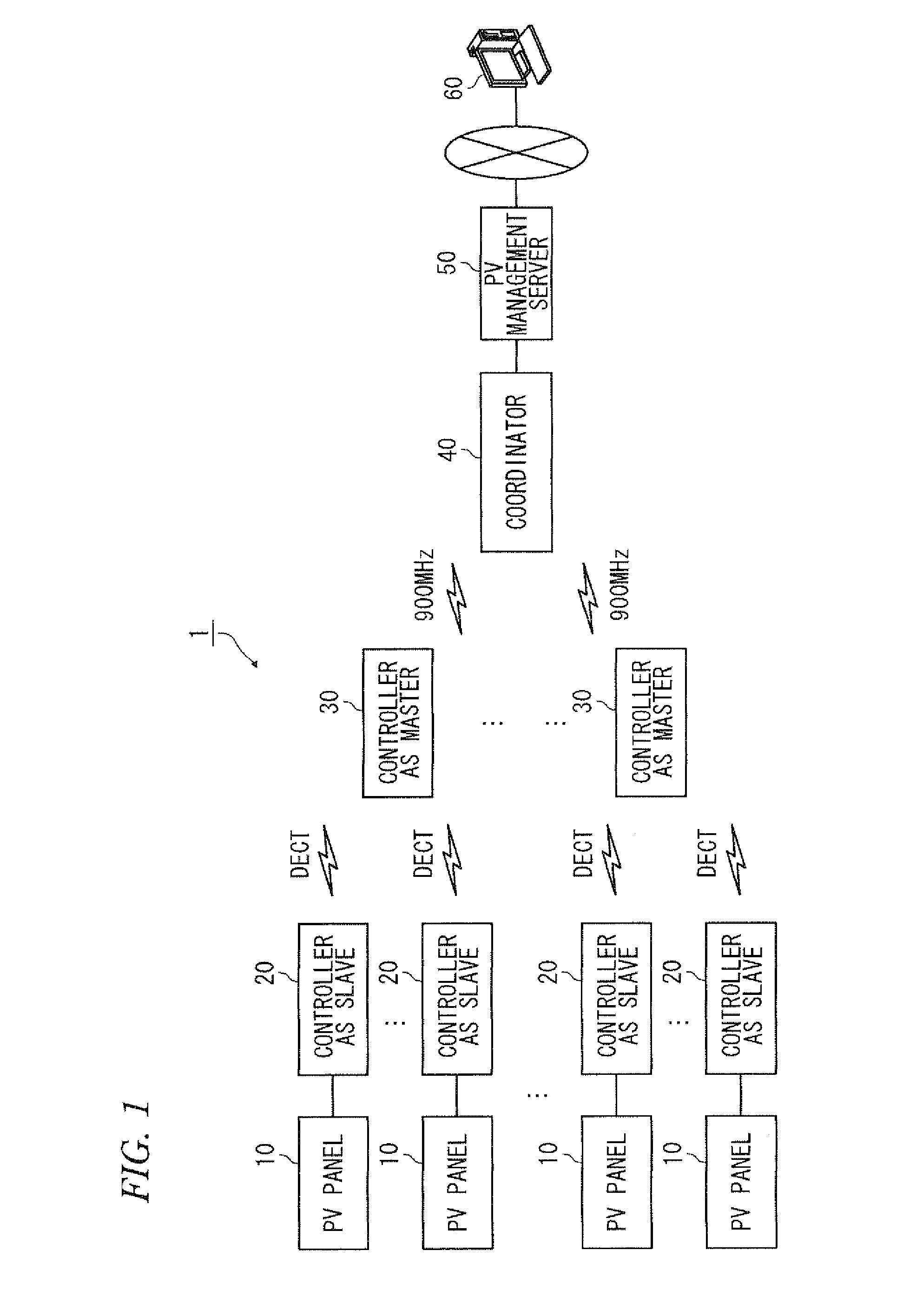
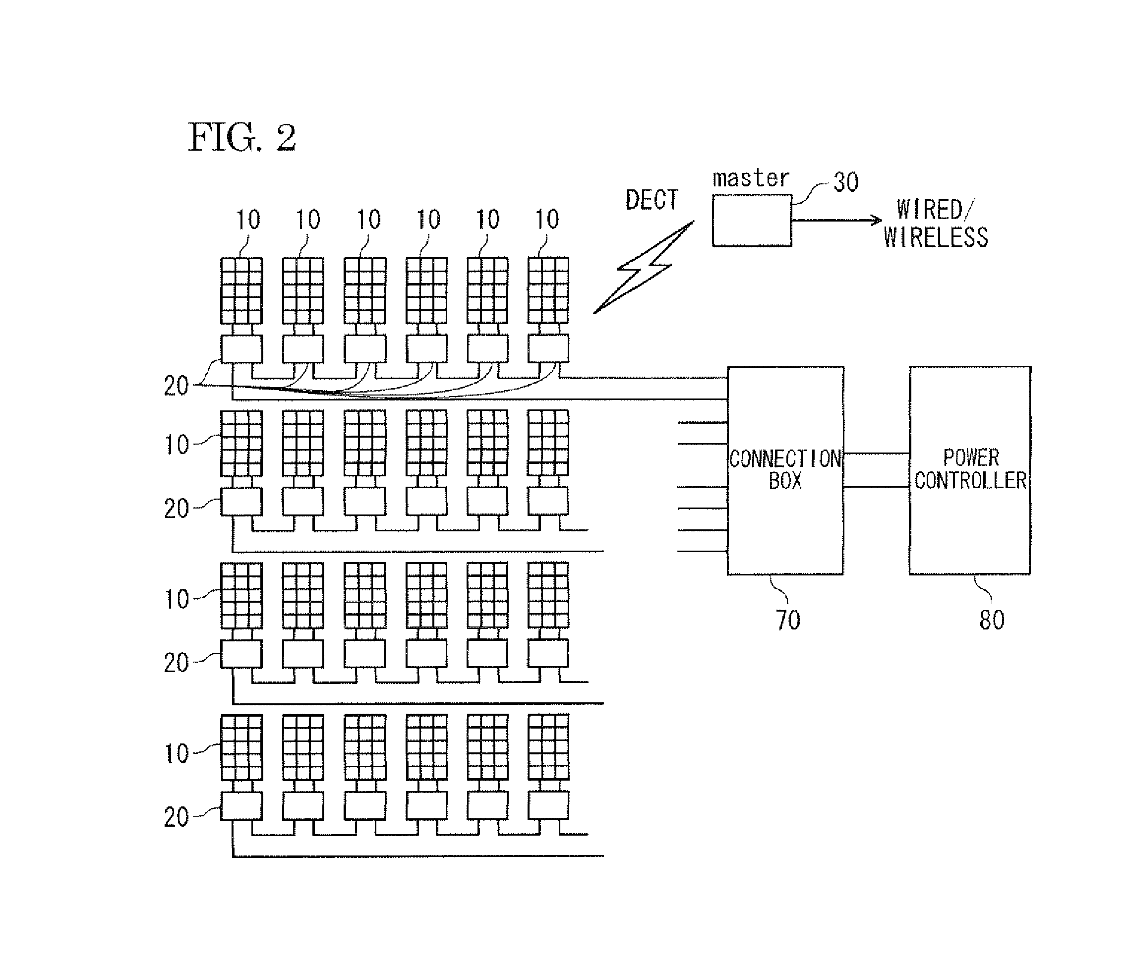
[0045]FIG. 1 is a diagram illustrating an overall sunlight electricity generation system according to embodiments of the present invention. A sunlight electricity generation system 1 is an example of the power generation system, and includes a plurality of sunlight panels (photovoltaic (PV) panels) 10. Each of the sunlight panels 10 is connected to a controller 20. The controller 20 has a function of the maximum power point tracker (MPPT), described later. A plurality of controllers 20 function as slaves and are managed by a controller 30 which functions as a master. Communication using Digital Enhanced Cordless Telecommunications (DECT; registered trademark) is performed between the controllers 20 and 30. In the following description, the controller 20 is referred to as an “MPPT device 20”. The MPPT device 20 is an example of the voltage conversion apparatus.

[0046]A coordinator 40 collectively manages a plurality of controllers 30 by using, for example, wireless communication of 90...

embodiment 2

[0062]FIG. 4 is a block diagram of an MPPT device according to Embodiment 2. Embodiment 2 is different from Embodiment 1 in that the MPPT device 20B is separable into two units including a bypass unit 20B1 and a conversion unit 20B2 as shown in FIG. 4. The same constituent element is given the same reference numeral as in FIG. 3, and description thereof will be omitted.

[0063]The bypass unit 20B1 includes an ON / OFF switching portion 21, a switching control portion 22, and a power supply portion 231. A pair of connection terminals 26, 26 are respectively provided in paths between a pair of input connectors and the ON / OFF switching portion 21. In addition, a pair of connection terminals 27, 27 are respectively provided in paths between a pair of output connectors and the ON / OFF switching portion 21. The switching control portion22 is provided with a switching signal terminal to which a panel mode switching signal can be input. The respective constituent elements (the ON / OFF switching p...

embodiment 3

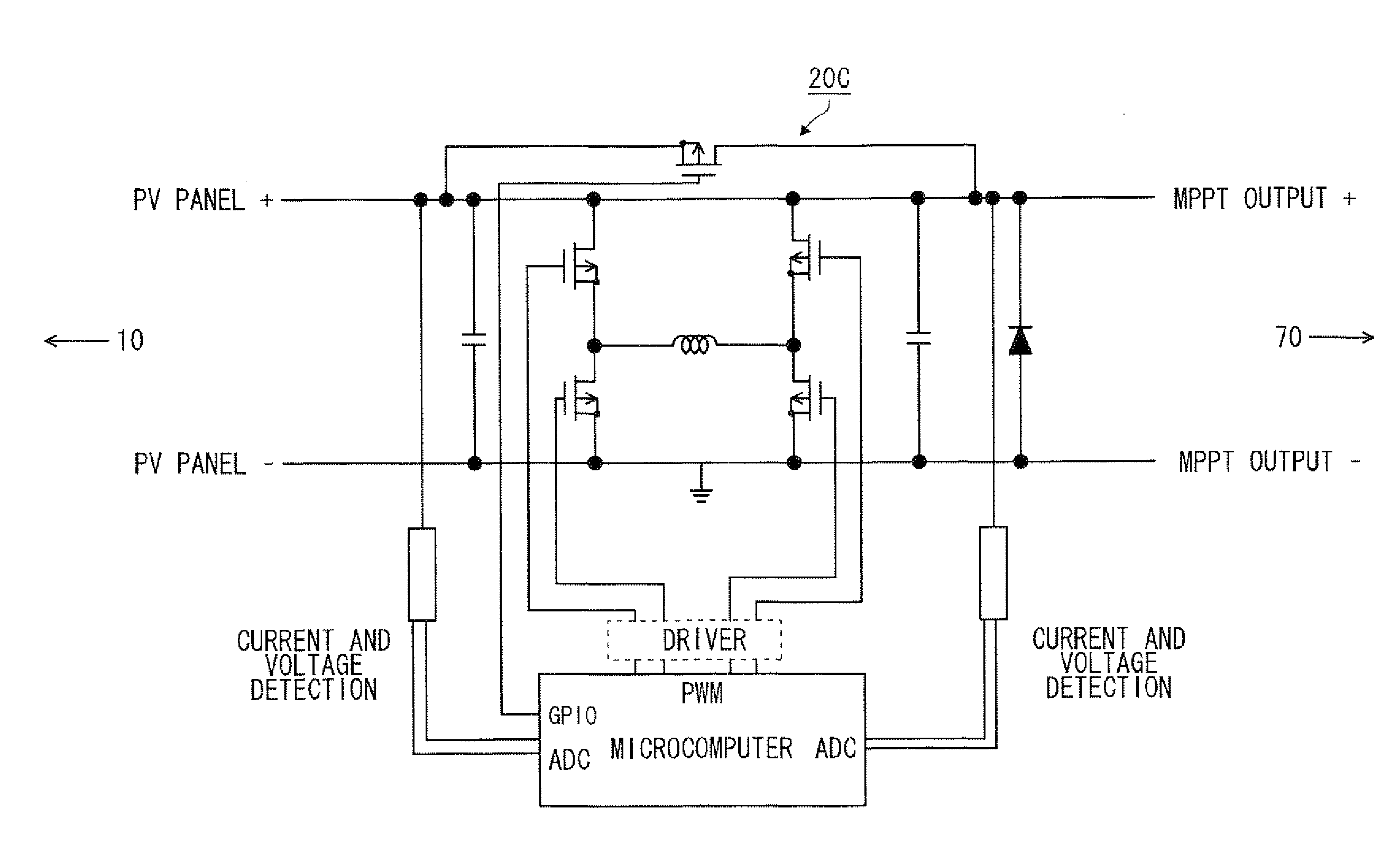
[0071]FIG. 5 is a circuit diagram of an MPPT device according to Embodiment 3. A microcomputer and a driver of an MPPT device 20C correspond to the control portion 25 of FIG. 3. Four MOSFETs connected to an inductor of the MPPT device 20C correspond to the DC / DC portion 24 of FIG. 3. A MOSFET (the upper part of FIG. 5) of the MPPT device 20C corresponds to the ON / OFF switching portion 21 of FIG. 3. In the MPPT device 20C according to this Embodiment 3, the MOSFET corresponding to the ON / OFF switching portion 21 is turned on in the same manner as in Embodiments 1 and 2 in a case where the MOSFETs forming the DC / DC portion or the microcomputer is not being operated normally. In addition, in Embodiment 3, control by the ON / OFF switching portion 21 is not necessarily required.

[0072]FIGS. 6A and 6B are diagrams illustrating an operation example of a sunlight electricity generation system according to Embodiment 3. The sunlight electricity generation system includes four strings ST1, ST2,...


PUM


Abstract

A voltage conversion apparatus converts a voltage of an electricity generator. The voltage conversion apparatus includes a maximum power tracking portion that is adapted to output a voltage which is output by the electricity generator to an external device at a predetermined ratio such that an operation point of the electricity generator tracks an optimal operation point at which power of the electricity generator reaches a maximum level, and a voltage output portion that is adapted to output a voltage which is output by the electricity generator to the external device when the maximum power tracking portion is not being operated normally.

Description

BACKGROUND[0001]1. Technical Field[0002]The present invention relates to a maximum power point tracker used for electricity generation such as sunlight electricity generation, and particularly to a voltage conversion apparatus, a power generation system, and a voltage conversion method capable of suppressing a reduction in electricity generation efficiency.[0003]2. Background Art[0004]In recent years, sunlight electricity generation using sunlight energy which is eco-friendly and clean energy has attracted attention. An output of the sunlight electricity generation fluctuates depending on various conditions such as the seasons, time zones, and weather conditions and thus repeatedly rises and falls at all times. The maximum power point tracker (MPPT) is known which maximizes the output by controlling a voltage and a current at an appropriate balance.[0005]In a centralized management method in which a plurality of sunlight panels are controlled by a single MPPT, there are cases where,...

Claims


Application Information

Patent Timeline
Patent Type & Authority Applications(United States)
IPC IPC(8): H02J1/00
CPCH02J1/00G05F1/67H02M3/1584H02J2300/10H02J2300/26H02J3/381Y02E10/56H02J3/46
Inventor NOSAKA, SHIGEKIYOKOGA, HISAO
Owner PANASONIC INTELLECTUAL PROPERTY MANAGEMENT CO LTD
Why Eureka
Try Eureka