Microwave assisted magnetic recording head and magnetic data storage apparatus

a technology of microwave assisted magnetic recording and magnetic data storage, which is applied in the direction of data recording, instruments, and heads with metal sheet cores, etc., can solve the problems of increasing the difficulty of writing data to magnetic disk media in a smaller track width or bit length, becoming more difficult to record data on magnetic disk media, and reducing the intensity of recording magnetic field. , to achieve the effect of preventing high-frequency magnetic field, preventing spread not only, and increasing the real density

Inactive Publication Date: 2013-12-12
HITACHI LTD
View PDF18 Cites 14 Cited by
  • Summary
  • Abstract
  • Description
  • Claims
  • Application Information

AI Technical Summary

Benefits of technology

[0014]The structure of the periphery of the spin torque oscillator 40 will be specifically described using the schematic structural view of the air bearing surface shown in FIG. 19. The trailing shield layer 24, which serves as an electrode, is in contact with the top of the spin torque oscillator 40, and the main pole 22, which is serves as another electrode, is in contact with the bottom of the spin torque oscillator 40. The trailing shield layer 24 and the main pole 22 are electrically insulated in portions other than the portion of the spin torque oscillator 40. A side / leading shield layer 26 is provided around the main pole 22, which is the lower electrode, with a conductive sidegap layer 27 interposed therebetween. The side / leading shield layer 26 has a function of reducing the lead resistance and suppressing a spread of a recording magnetic field from the main pole 22.
[0016]The difference between the microwave assisted magnetic recording head and the perpendicular magnetic recording head seen in their cross-sectional structures lies in the fact that the microwave assisted magnetic recording head has the spin torque oscillator 40 arranged on the air bearing surface 100, while the perpendicular magnetic recording head does not, and that the perpendicular magnetic recording head has a back contact portion 29 arranged between a yoke portion 23 and an upper magnetic pole 25, while the microwave assisted magnetic recording head does not. With regard to the structure of the air bearing surface, the microwave assisted magnetic recording head has the spin torque oscillator 40 arranged between the main pole 22 and the trailing shield layer 24, while in the perpendicular magnetic recording head, the width of a top gap layer 28 between the main pole 22 and the trailing shield layer 24 in the track width direction is narrow, the trailing shield layer 24 is in direct contact with the side / leading shield layer 26, and the periphery of the main pole 22 is entirely surrounded by the shield layers. When such a structure is employed, it becomes possible to suppress an excessive spread of a recording magnetic field generated from the main pole 22.
[0018]The present invention provides a microwave assisted magnetic recording head that can write narrower or shorter recording bits and read information more stably by suppressing a spread of not only a recording magnetic field generated from a main pole but also a high-frequency magnetic field generated from a spin torque oscillator.
[0024]According to the present invention, it is possible to suppress a spread of not only a recording magnetic field generated from a main pole but also a high-frequency magnetic field generated from a spin torque oscillator in the track width direction or the down-track direction, whereby narrower or shorter bits can be recorded on disk media. That is, a microwave assisted magnetic recording head that is adapted to higher a real density can be provided.
[0025]In addition, when a high-frequency magnetic field shield layer is arranged between a spin torque oscillator and a read sensor, it is possible to prevent a high-frequency magnetic field from oscillating magnetization of a longitudinal biasing layer of a read device. Thus, stable operations without fluctuations of the read properties can be performed.

Problems solved by technology

However, it has become increasingly difficult to write data to magnetic disk media in a smaller track width or bit length and read data from magnetic disk media.
In particular, with a reduction in the size of a main pole, which generates a recording magnetic field, of a recording head, the intensity of the recording magnetic field would decrease, so that it would become more difficult to record data on magnetic disk media.
Although shingled magnetic recording (SMR) in which overwriting is performed while a wide main pole is gradually shifted by an amount of a track pitch is considered to be used for practical applications, it is not considered that the attainable a real density will increase significantly as the thermal stability of magnetic disk media cannot be improved significantly.

Method used


Image

  • Microwave assisted magnetic recording head and magnetic data storage apparatus
  • Microwave assisted magnetic recording head and magnetic data storage apparatus
  • Microwave assisted magnetic recording head and magnetic data storage apparatus

Examples


embodiment 1

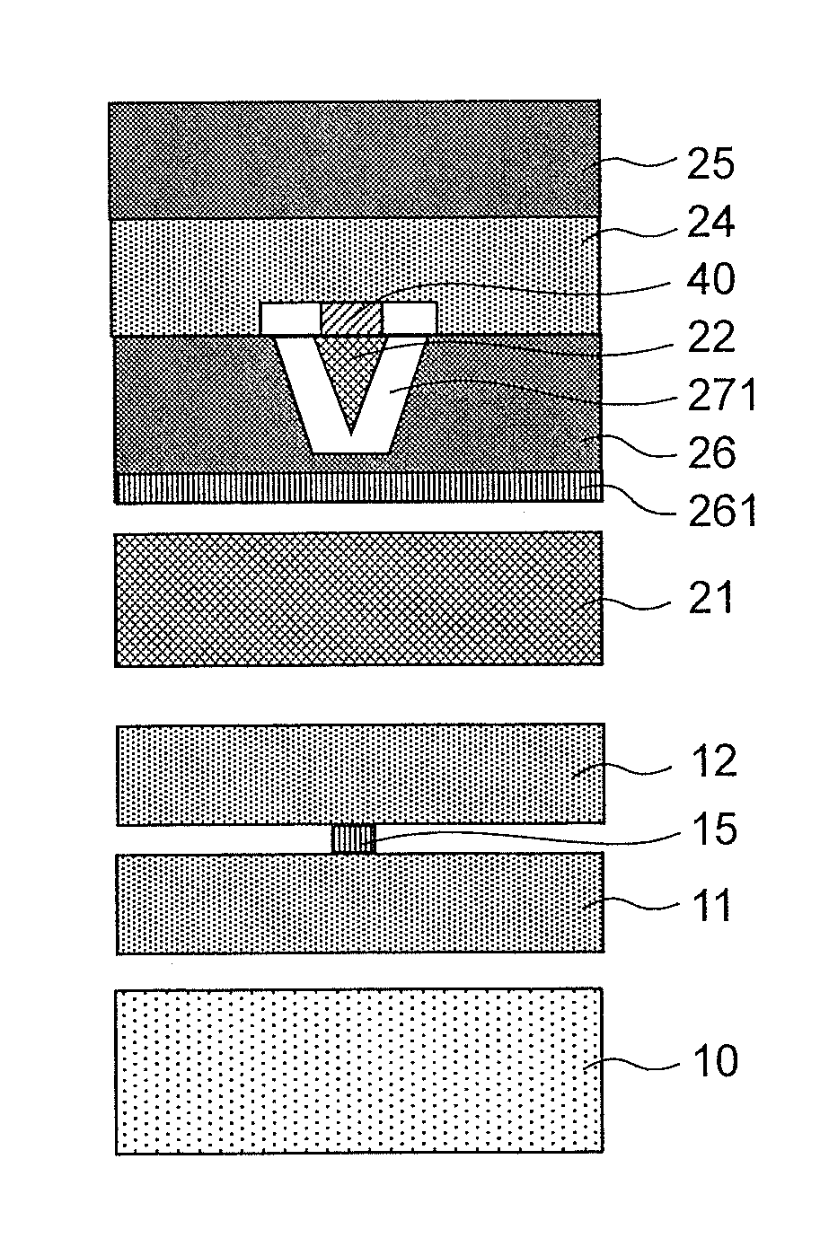
[0065]FIG. 10 is a schematic view showing an exemplary structure on an air bearing surface of a microwave assisted magnetic recording head of the present invention. The recording head of this embodiment basically has a head structure including the insulator sidegap layer 271 shown in FIG. 22, and also has a sideshield layer 241 for a high-frequency magnetic field provided between the trailing shield layer 24 and the side / leading shield layer 26. Accordingly, it is possible to control both a spread of a recording magnetic field from the main pole 22 and a spread of a high-frequency magnetic field from the spin torque oscillator 40. It should be noted that even when a high-frequency magnetic field from the spin torque oscillator 40 acts on the sideshield layer 241 for a high-frequency magnetic field, magnetization of the sideshield layer 241 for a high-frequency magnetic field does not oscillate as the volume thereof is large. Thus, this does not become a cause of adjacent track inter...

embodiment 2

[0069]FIG. 13 is a schematic view showing another exemplary structure on an air bearing surface of a microwave assisted magnetic recording head of the present invention. In this embodiment, a trailing shield layer 242 for a high-frequency magnetic field is arranged in part of the trailing shield layer 24 such that it is in contact with the spin torque oscillator 40. Accordingly, a field gradient of a high-frequency magnetic field in the down-track direction becomes large, whereby a bit having a sharp magnetic transition can be recorded. Thus, resolution in the down-track direction can be improved.

[0070]Alternatively, as shown in FIG. 14, it is also possible to provide the trailing shield layer 242 for a high-frequency magnetic field above the spin torque oscillator 40 with a material, which constitutes the trailing shield layer 24, interposed therebetween. When such a structure is employed, it is possible to increase a field gradient in the down-track direction of a recording magnet...

embodiment 3

[0071]FIG. 15 is a schematic view showing another exemplary structure on an air bearing surface of a microwave assisted magnetic recording head of the present invention. In this embodiment, a leading shield layer 261 for a high-frequency magnetic field is arranged in part of the side / leading shield layer 26, at a position between the spin torque oscillator 40 and the read sensor 15.

[0072]The read sensor 15 for reading information recorded on a magnetic disk medium is provided with a longitudinal biasing layer for performing a stable read operation, and the longitudinal biasing layer is typically formed of a hard magnetic material. When a high-frequency magnetic field from the spin torque oscillator 40 reaches the longitudinal biasing layer of the read sensor 15, it is concerned that magnetization of the longitudinal biasing layer would wobble and the longitudinal biasing field would fluctuate; thus, the read operation may become unstable. This can be avoided by arranging the leading...


PUM

PropertyMeasurementUnit
recording magnetic fieldaaaaaaaaaa
frequency magnetic fieldaaaaaaaaaa
magnetic fieldaaaaaaaaaa

Abstract

To suppress a spread of not only a recording magnetic field generated from a main pole but also a high-frequency magnetic field generated from a spin torque oscillator in a microwave assisted magnetic recording head. The main pole and the spin torque oscillator are surrounded by a trailing shield layer and are also surrounded by a side / leading shield layer with an insulator sidegap layer interposed therebetween, and a high-frequency magnetic field shield layer, which absorbs a high-frequency magnetic field generated from the spin torque oscillator, is arranged in at least part of the shield layers.

Description

CLAIM OF PRIORITY[0001]The present application claims priority from Japanese patent application JP 2012-130764 filed on Jun. 8, 2012, the content of which is hereby incorporated by reference into this application.BACKGROUND[0002]1. Technical Field[0003]The present invention relates to a microwave assisted magnetic recording head that adopts a microwave assisted magnetic recording scheme, and a hard-disk drive having the head mounted thereon.[0004]2. Background Art[0005]In recent years, the a real density of HDD (hard-disk drive) has been steadily increasing with the adoption of a perpendicular magnetic recording scheme, and is now about to reach 1 Tb / in2. However, it has become increasingly difficult to write data to magnetic disk media in a smaller track width or bit length and read data from magnetic disk media. In particular, with a reduction in the size of a main pole, which generates a recording magnetic field, of a recording head, the intensity of the recording magnetic field ...

Claims


Application Information

Patent Timeline
Patent Type & Authority Applications(United States)
IPC IPC(8): G11B5/147
CPCG11B5/147G11B5/314G11B5/3146G11B5/315G11B2005/0024
Inventor WATANABE, KATSUROIGARASHI, MASUKAZU
Owner HITACHI LTD
Why Eureka
Try Eureka