Apparatus and method for well logging and data processing device

a well and data processing technology, applied in the field of well logging, can solve the problems of inability to use dc electrical logging method, inapplicability of lwd lateral resistivity logging in said cases, and high resistivity logging, so as to achieve the highest effective drilling catching rate, improve drilling quality, and direct and accurate

Active Publication Date: 2013-12-19
CHINA PETROCHEMICAL CORP +1
View PDF1 Cites 5 Cited by
  • Summary
  • Abstract
  • Description
  • Claims
  • Application Information

AI Technical Summary

Benefits of technology

[0021]Compared to the radial-depth investigation, the axial-depth investigation according to the invention possesses the following advantages.
[0022]First of all, the axial-depth investigation according to the invention may effectively control the trajectory of the inclination-made section in drill engineering. The well known measurement of horizontal segment of formation usually assumes a horizontal layered distribution, when deflection begins, the apparatus for resistivity logging is almost perpendicular to the horizontal layered formations. Therefore, the response of radial investigation can only reflect the variation in resistivity of the measured formation at certain layer, while the response of axial investigation has a plurality of axial layers of investigation, which may reflect the variation in resistivity of the measured formation at multiple different drilling depths, effectively identify formation boundary and oil-water contact, and adjust the deflection radian to make it accurate and smooth, thus improve the drilling quality in the inclination section.
[0023]Further, when the drilling bit enters a complicated highly-deviated well or horizontal section, the axial-depth investigation according to the invention may perform axial investigation at different depths on the formations along the direction of drilling movement. Therefore, it is more direct and accurate as compared to the method of radial investigation, and it can predetermine a thin reservoir, a complicated folded and interlaid bed, whereby effectively keeping away from faults, drilling to a long distance along high-dip reservoirs and obtaining a highest effective drilling catching rate for oil and gas.
[0024]The method for well logging according to the invention and the corresponding data processing apparatus may measure in real time the variation characteristics of the variation ratio of the formation resistivity in the drilling process, discriminate in real time the formation boundary and oil-water interface, and capture the best opportunity of entering the oil and gas reservoir. Moreover, the method may predict the geological information in front of the drill bit much earlier, adjust the trajectory of the borehole timely in high-dip and anisotropic-formation horizontal wells, and control the drill tool to pass through the best location of the petroleum reservoir so as to obtain the largest oil contact face. Therefore, it is extremely adaptive to geo-steering in petroleum engineering.

Problems solved by technology

However, the above-mentioned apparatus for LWD lateral resistivity logging has deficiencies as follows: since the technique of lateral resistivity logging belongs to the method of DC electrical logging, that is to say, it needs to have a power supply electrode to conduct DC current into a formation, and then use a measuring electrode to measure the electrical potential at certain point in the well, thus such lateral resistivity logging method may be used only when there is conductive mud in the well that provides current channels.
In such cases, the DC electrical logging method cannot be used, that is, the method of LWD lateral resistivity logging is no longer applicable in said cases.
However, although the various apparatuses for LWD electromagnetic wave propagation resistivity logging at present may measure resistivity at different depths of investigation, they have deficiencies as follows.
Firstly, the signal frequency used by the apparatus for LWD electromagnetic wave propagation resistivity logging is too high, the depth of investigation is limited due to the propagation effect of the electromagnetic wave.
Thirdly, since the coil system of the apparatus for LWD electromagnetic wave propagation resistivity logging is wound on the surface of the drill collar, the manufacture process thereof is rather complicated.
Moreover, the coil system may be easily abraded and thus be damaged during operating.
Then, when the size of the borehole varies, it needs to rewind the coils, thus the maintenance and overhaul is rather complicated and the maintenance cost is high.
Besides, similar to the apparatus for LWD lateral resistivity logging, the apparatus for LWD electromagnetic wave propagation resistivity logging is unable to work in oil-based mud.
However, such an apparatus for LWD induction resistivity logging further has deficiencies as follows.
Since the apparatus employs a coil system composed of one transmitting coil and two receiving coils and having a single fixed depth of investigation, said apparatus may only provide the resistivity of formation in one radial depth of investigation, while cannot be used to explain complicated invasive profile and to separate the corrosive formations.
Besides, as for a corrosive formation, mud invasion causes the resistivity thereof to vary in radial directions, since only a resistivity value in one radial depth of investigation can be obtained at a measurement point in the same depth, the apparatus for LWD induction resistivity logging cannot be used to explain the invasion condition of the formation, and the condition where the formation is invaded by mud and the reservoir permeability cannot be determined.
This is disadvantageous for explanation of oil and gas reservoirs, thus it cannot be used to calculate the true formation resistivity accurately.
However, the apparatus for LWD induction resistivity logging at present is unable to meet the requirement.
As a result, it is hard to carry out such a LWD induction resistivity logging manner during the practical application.

Method used


Image

  • Apparatus and method for well logging and data processing device
  • Apparatus and method for well logging and data processing device
  • Apparatus and method for well logging and data processing device

Examples


Embodiment Construction

[0039]Some terms are used for denoting specific system components throughout the application document. As would be appreciated by those skilled in the art, different designations may usually be used for denoting the same component, thus the application document does not intend to distinguish those components that are only different in name rather than in function. In the application document, terms “comprise”, “include” and “have” are used in the opening way, and thus they shall be construed as meaning “comprise but not limited to . . . ”. Besides, Terms “substantially”, “essentially”, or “approximately”, that may be used herein, relate to an industry-accepted tolerance to the corresponding term. The term “coupled”, as may be used herein, includes direct coupling and indirect coupling via another component, element, circuit, or module where, for indirect coupling, the intervening component, element, circuit, or module does not modify the information of a signal but may adjust its cu...


PUM


Abstract

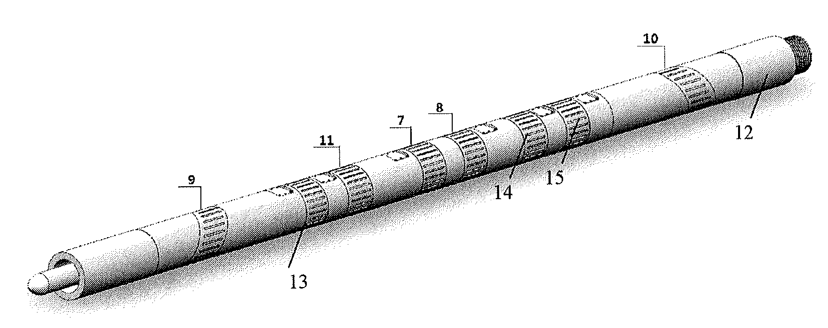
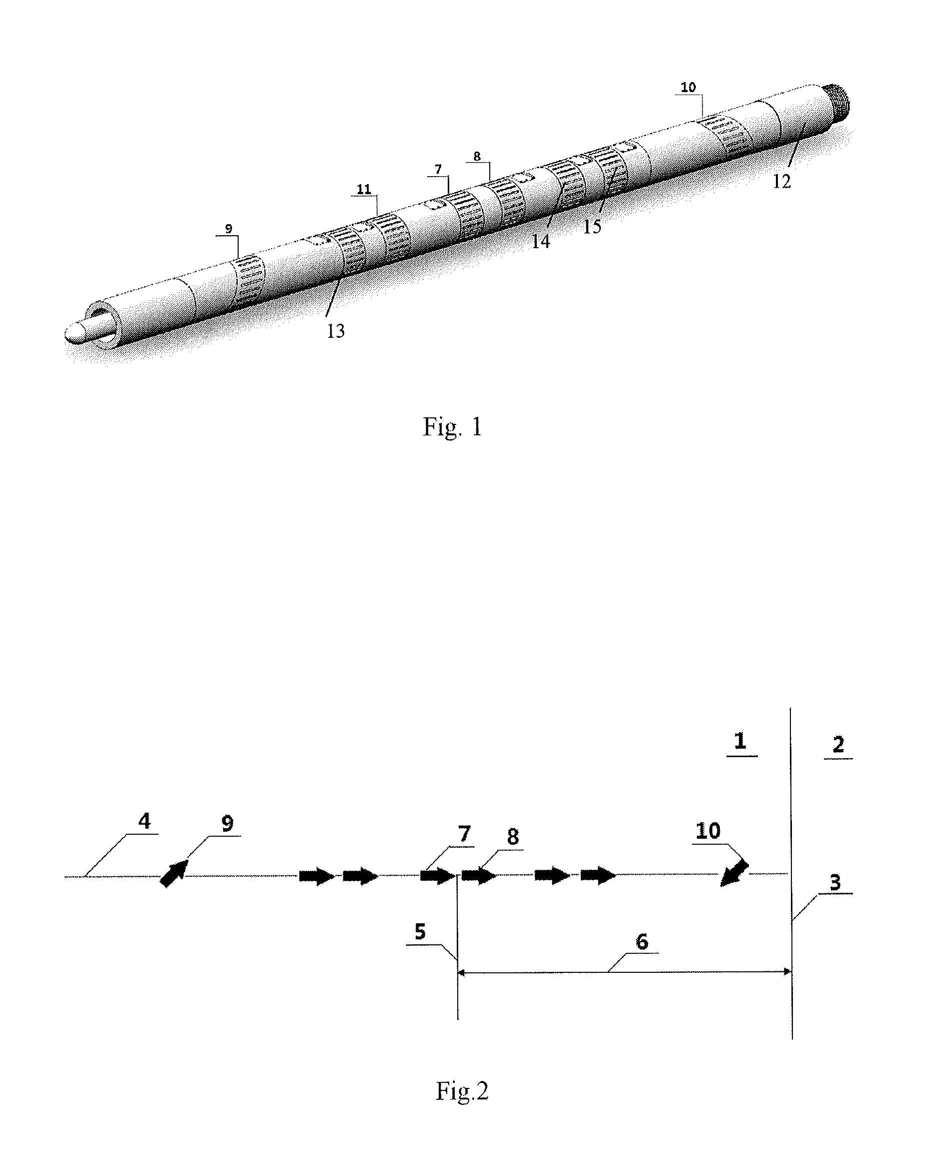
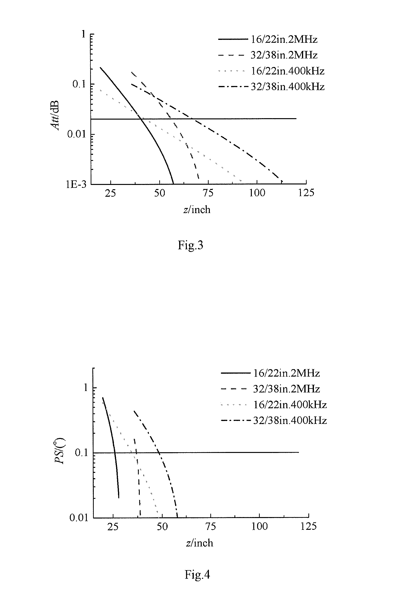
The disclosure relates to an apparatus and a method for well logging as well as a data processing device thereof. Said apparatus for well logging comprises a drill collar body and an array of antennas, wherein said array of antennas comprises at least a pair of transmitting antenna and receiving antenna, said transmitting antenna and receiving antenna are configured for generating a curve of axial forward depth of investigation. By employing the method for well logging according to the present invention, not only the variation of resistivity in the axial forward formation may be measured in real time during the drilling, but also the interfacial characteristics of the axial forward formations having different resistivity may be discriminated during drilling.

Description

TECHNICAL FIELD[0001]The invention relates to the technical field of well logging, more specifically, the invention relates to the technical field of measurement while drilling (i.e. MWD) in the drilling industry. In particular, the invention relates to an apparatus and method for well logging as well as a data processing device thereof.BACKGROUND OF THE INVENTION[0002]At present, in the art of MWD in the drilling industry such as the explorating of oil and gas, coalbed methane, shale gas trapped within shale formations, drilling, mining and so on, the formation resistivity is generally used to form stratigraphic profiles and to determine oil saturation, gas content from coal structure and mineral fractures of reservoirs, thus the formation resistivity is a primary basis for explaining and evaluating oil and gas, coal, mineral reserves in well logging. The currently known logging-while-drilling (LWD) resistivity logging technique includes LWD lateral resistivity logging, LWD electro...

Claims


Application Information

Patent Timeline
Patent Type & Authority Applications(United States)
IPC IPC(8): G01V3/28
CPCG01V3/28G01V3/30G01V3/08E21B7/04E21B49/00
Inventor YANG, JINZHOULI, ZUOHUILI, NANWEI, BAOJUNLIU, QINGLONGXIAO, HONGBING
Owner CHINA PETROCHEMICAL CORP
Why Eureka
Try Eureka