
Exhaust gas recycling control system of combustion device

Inactive Publication Date: 2013-12-26
SHENG ZHUN ENTERPRISE
View PDF4 Cites 5 Cited by
  • Summary
  • Abstract
  • Description
  • Claims
  • Application Information

AI Technical Summary

Benefits of technology

The present invention is an exhaust gas recycling control system for a combustion device that reduces energy consumption and carbon dioxide emissions. It achieves this by measuring the amount of oxygen in the exhaust gas and using it to control the flow of exhaust gas recycling. This system reduces the amount of heat lost and the need for external cold air, resulting in energy savings and a reduction in carbon dioxide emissions. Additionally, it helps prevent air pollution and global warming.

Problems solved by technology

Due to the rising of the oil and electricity prices and the greenhouse effect, energy-saving and carbon reduction have become serious issues in our life and industry, especially in industry.
However, a lot of exhaust gas is inevitably generated during the combustion process of these devices, and is constantly emitted to the atmosphere.
2. The continuous emission of the exhaust gas of 150° C. to 280° C. causes continuous loss of the temperature of a combustion chamber; such that, the fuel and cold air must be continually add into the device, resulting in increasing costs.
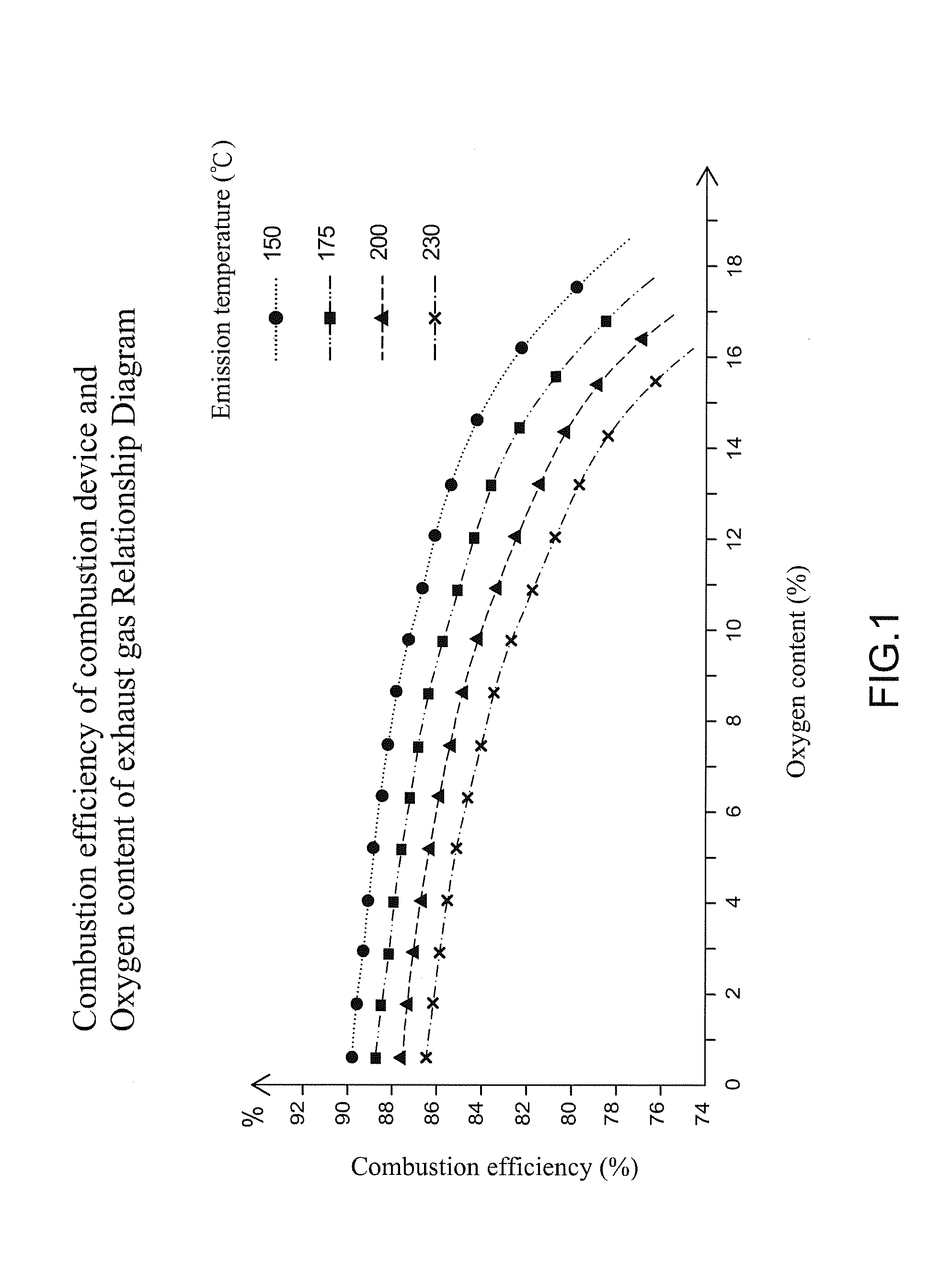
3. The average oxygen content of the above-mentioned exhaust gas is over 9%, even up to 18%. The boiler, for example, FIG. 1 shows the relationship between the combustion efficiency of the conventional combustion device and the oxygen content of the exhaust gas, and the emission temperature respectively is 150° C., 175° C., 200° C., and 230° C. FIG. 1 shows that the higher is the oxygen content O2%, the lower is the combustion efficiency, resulting in a part of the heat energy of the fuel is taken away by the excess air. Generally, every 3% of the oxygen content in the exhaust gas is decreased; about 1% to 2% of the fuel is saved.
However, the oxygen content emission of the exhaust gas is still high, and the high-temperature exhaust gas (150° C. to 280° C.) cannot be recycled, which is a kind of waste.

Method used


Image

  • Exhaust gas recycling control system of combustion device
  • Exhaust gas recycling control system of combustion device
  • Exhaust gas recycling control system of combustion device

Examples


Embodiment Construction

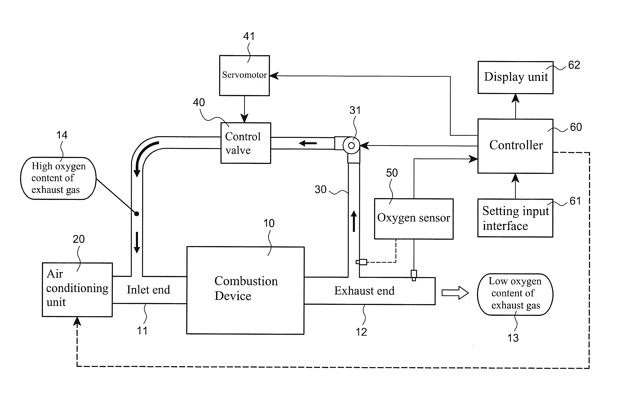
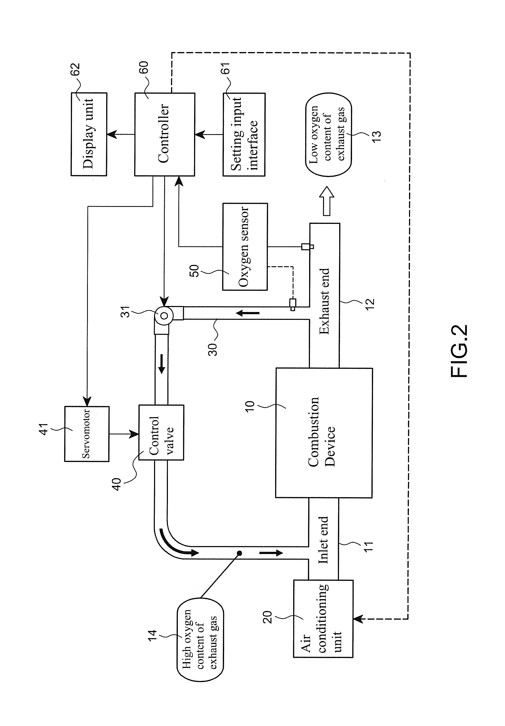
[0019]Referring to FIG. 2, the preferred embodiment of an exhaust gas recycling control system of combustion device in accordance with the present invention comprises: a combustion device 10 includes a boiler, an incinerator, and a power generation device . . . etc., which has a combustion chamber and an exhaust device. The combustion device 10 has an inlet end 11 at a front side thereof and an exhaust end 12 at a reserve side thereof to discharge an exhaust gas of the combustion device 10. Moreover, an air conditioning unit 20 is arranged in front of the inlet end 11. For example, the air conditioning unit 20 may be a blower of a burner (not shown) to provide cold air containing about 21% of the oxygen for the combustion device 10. However, it is a prior art and thus will not be described in details here.

[0020]The present invention is characterized in that the exhaust end 12 is connected with a recycling tube 30 to the inlet end 11, and the recycling tube 30 includes at least a con...


PUM


Abstract

An exhaust gas recycling control system includes a combination device, having inlet and exhaust ends. The exhaust end is connected to the inlet end by a recycling tube which has a control valve to control an open or closed state. An oxygen sensor mounted detects oxygen content in an exhaust gas and convert the oxygen content detected signal into a voltage signal sent to a controller. The controller controls the control valve to open or close. When the oxygen content of the exhaust gas is higher than a threshold, the control valve opens and a high oxygen content of exhaust gas flows through the recycling tube to the inlet end.

Description

BACKGROUND OF THE INVENTION[0001]1. Field of the Invention[0002]The invention relates to an exhaust gas recycling control system of combustion device, and more particularly to an oxygen content of exhaust gas as a control of the opening or closing the backflow path.[0003]2. Description of the Related Art[0004]Due to the rising of the oil and electricity prices and the greenhouse effect, energy-saving and carbon reduction have become serious issues in our life and industry, especially in industry. The fuel as an energy source is required for all kinds of boilers, incinerators, power generation device, etc. However, a lot of exhaust gas is inevitably generated during the combustion process of these devices, and is constantly emitted to the atmosphere. A boiler as an example has the following drawbacks:[0005]1. Generally, the emission temperature of a boiler is between 150° C. and 208° C. Such a high temperature of exhaust gas emitted to the atmosphere not only causes air pollution but...

Claims


Application Information

Patent Timeline
IPC IPC(8): F23C9/00F23N1/00
CPCF02D41/1454F02D41/0052F23N5/006F23C9/00F23C2202/30F23C2202/50F23G2900/00001F02D2021/083F02M26/46F23N2221/12Y02T10/40F23B80/02F23B90/00F23J11/00
Inventor LIAO, CHIU-HUEI
Owner SHENG ZHUN ENTERPRISE
Learn More