

Iron oxide and silica magnetic core
a technology of iron oxide and silica, applied in the field of magnetic core, can solve the problems of high core loss, hysteresis loss, energy loss of core material, etc., and achieve the effects of high temperature tolerance, good mechanical properties, and increased green strength
- Summary
- Abstract
- Description
- Claims
- Application Information
AI Technical Summary
Benefits of technology
Problems solved by technology
Method used
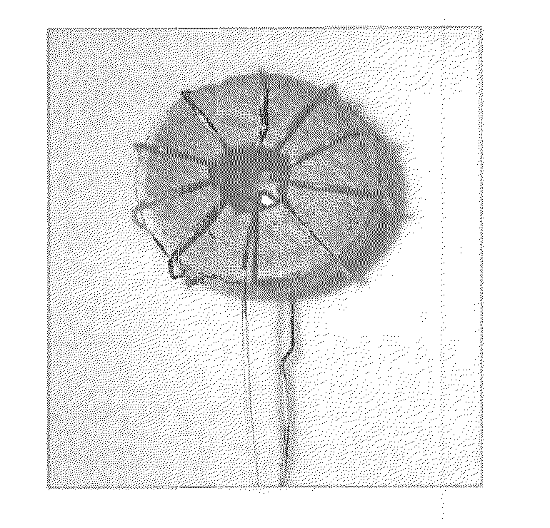
Image

Examples
examples
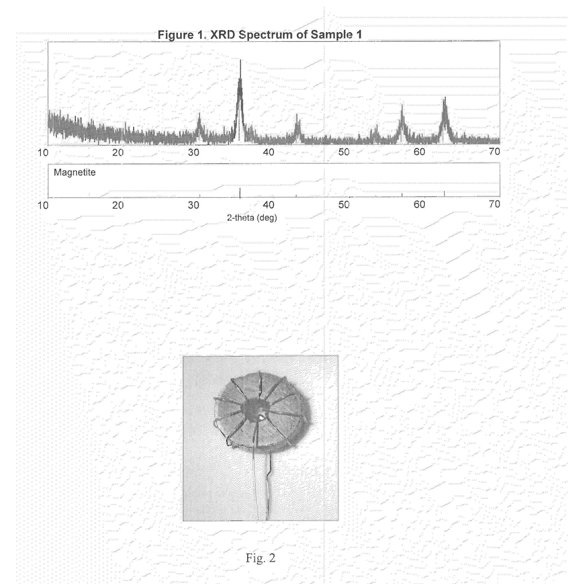
[0051]Core / shell Fe3O4 / SiO2 nanoparticles were synthesized as follows: iron trichloride and iron dichloride were co-dissolved in water. The addition of NH4OH / H2O initiated the iron oxide nanoparticle formation. Tetraethyl orthosilicate, catalyzed by triethylamine, was then used to deposit the silica shell onto the magnetite nanoparticles.
[0052]The Fe3O4 / SiO2 core / shell nanoparticles were sintered under heat and pressure with a flowing argon atmosphere, using graphite punch and dies.
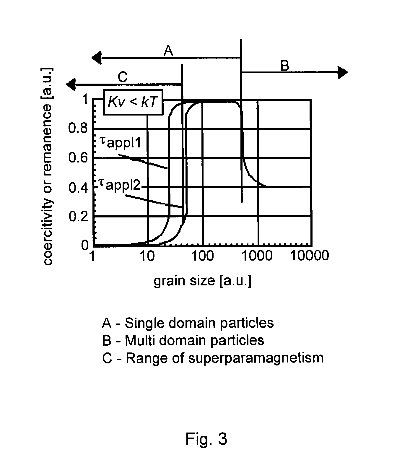
[0053]Because a magnetic material is only superparamagnetic when the grain size is near or below the magnetic domain size (˜25 nm for magnetite), the nanoparticle core must be maintained as small as possible, or the sample will become ferromagnetic, and express magnetic hysteresis. Therefore, the most mild and gentle sintering conditions that still yield a monolithic sample that is robust enough to be machined into a toroid are desired, because more aggressive sintering conditions will promote unwanted gr...
PUM
| Property | Measurement | Unit |
|---|---|---|
| particle size | aaaaa | aaaaa |
| particle size | aaaaa | aaaaa |
| grain size | aaaaa | aaaaa |
Abstract
Description
Claims
Application Information