NAND flash biasing operation

a biasing operation and flash memory technology, applied in the field of flash memory technology, can solve problems such as unwanted charge tunneling into cells, reducing, and arising from charge retention

Active Publication Date: 2013-12-26
MACRONIX INT CO LTD
View PDF1 Cites 19 Cited by
  • Summary
  • Abstract
  • Description
  • Claims
  • Application Information

AI Technical Summary

Benefits of technology

[0012]An integrated circuit is described including flash memory, that is configured for applying a bias arrangement including, (1) applying voltages to the unselected and selected word lines in a selected string of memory cells, (2) pre-charging the semiconductor body regions of strings of memory cells by coupling the semiconductor body regions of memory cells on both sides of the selected word line to a reference voltage, and (3) charging the sensing node to a sensing voltage while the switches between the strings and the sensing node are open so as to isolate the strings from the noise that is caused by setting up voltages on the sensing nodes. Capacitive boosting, as a result of transitions on unselected word lines during the time the string is isolated from the sensing node, is reduced or prevented by coupling the semiconductor bodies to the reference voltage during some or all of that time. The biasing arrangements usable to accomplish this condition can be applied in single layer, and multiple layer (e.g. 3D) memory arrays.

Problems solved by technology

As specifications for the values of target threshold voltages tighten for low voltage applications, and for applications that store multiple bits per cell, problems are arising with charge retention over many data sensing cycles.
Specifically, problems arise with minimizing the effects of noise that in the cells and preventing unwanted charge tunneling into memory cells by operations directed at other cells.
While this technique of opening the string select switch during bit line setup can limit the effects of noise on the memory cells, it can introduce another problem of unwanted charge tunneling into cells created through self-induced capacitive boosting within the strings of memory cells.
Such boosting in turn creates an electric field causing unwanted charge to tunnel into the selected cell or other cells, through hot carrier injection for example.

Method used


Image

  • NAND flash biasing operation
  • NAND flash biasing operation
  • NAND flash biasing operation

Examples


Embodiment Construction

[0034]A detailed description of embodiments of the present invention is provided with reference to FIGS. 1-14.

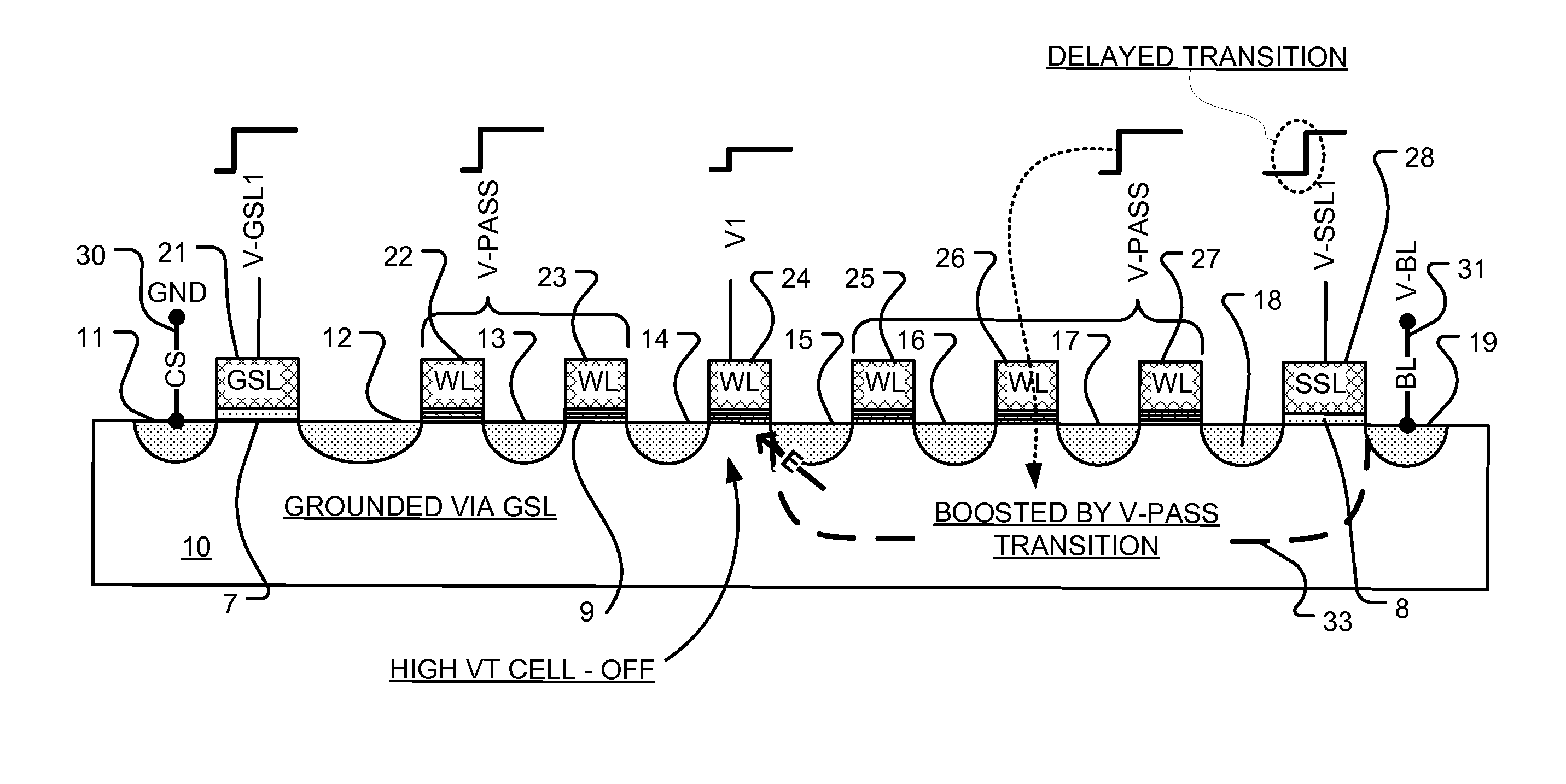
[0035]FIG. 1 is a simplified cross-sectional view of a selected NAND string that shows a bias arrangement. The NAND string includes a plurality of flash memory cells that are arranged in series. Another technology for implementation of NAND flash using bandgap engineered SONOS (BE-SONOS) charge trapping technology is described in U.S. Pat. No. 7,315,474 by Lue, which is incorporated by reference as if fully set forth herein. NAND strings can be implemented in a variety of configurations, including finFET technology, shallow trench isolation technology, vertical NAND technology and others. Yet another 3D NAND architecture is described in co-pending U.S. patent application Ser. No. 13 / 239,760 (now U.S. Patent Publication No. 2012-0182802) entitled “Memory Architecture of 3D Array With Improved Uniformity of Bit Line Capacitances” which application is incorporated by reference ...


PUM


Abstract

A charge storage memory is configured in a NAND array, and includes NAND strings coupled to bit lines via string select switches and includes word lines. A controller is configured to produce a bias for performing an operation on a selected cell of the NAND array. The bias includes charging the bit line while the string select switches are closed, such as to not introduce noise into the strings caused by such bit line charging. The semiconductor body regions in memory cells that are on both sides of the memory cells in the NAND strings that are coupled to a selected word line are coupled to reference voltages such that they are pre-charged while the word lines of the strings in the array are transitioned to various voltages during the operation.

Description

CROSS-REFERENCE TO RELATED APPLICATION[0001]Benefit is claimed of U.S. Provisional Application No. 61 / 661,852, filed 20 Jun. 2012.BACKGROUND OF THE INVENTION[0002]1. Field of the Invention[0003]The present invention relates to flash memory technology, and more particularly to flash memory suitable for high density implementations.[0004]2. Description of Related Art[0005]Flash memory is a class of nonvolatile integrated circuit memory technology. Traditional flash memory employs floating gate memory cells. Another type of memory cell used for flash memory can be referred to as a charge trapping memory cell, which uses a dielectric charge trapping layer in place of the floating gate.[0006]The typical flash memory cell consists of a field effect transistor FET structure having a source and drain separated by a channel, and a gate separated from the channel by a charge storage structure including a tunnel dielectric layer, the charge storage layer (floating gate or dielectric), and a bl...

Claims


Application Information

Patent Timeline
Patent Type & Authority Applications(United States)
IPC IPC(8): G11C16/06
CPCG11C16/06G11C16/0483G11C16/24G11C16/26H10B41/35H10B43/35G11C5/146G11C11/5642
Inventor CHEN, TI-WENLUE, HANG-TINGHUNG, SHUO-NANHUANG, SHIH-LINHSIEH, CHIH-CHANGCHANG, KUO-PIN
Owner MACRONIX INT CO LTD
Why Eureka
Try Eureka