Image forming apparatus

a technology of image forming apparatus and forming plate, which is applied in the direction of digital storage, instruments, and unauthorized memory use protection, etc., can solve the problem that double-sided printing may not be allowed in advance for this authenticated user

Active Publication Date: 2013-12-26
KYOCERA DOCUMENT SOLUTIONS INC
View PDF18 Cites 6 Cited by
  • Summary
  • Abstract
  • Description
  • Claims
  • Application Information

AI Technical Summary

Benefits of technology

[0007]An object of the present disclosure is to reduce the trouble for a user to change function setting if, when a certain user is authenticated in an initial state where there is no authenticated user, a function executable in an initial state is a function, the execution of which is not permitted for this authenticated user.

Problems solved by technology

However, in the above technology, if a public user performs user authentication after performing a setting operation to execute double-sided printing, for example, when it is determined by the public registration information to permit the execution of single-sided printing, but to deny the execution of double-sided printing for a public user, the execution of single-sided printing may be permitted, but the execution of double-sided printing may not be permitted in advance for this authenticated user.

Method used


Image

  • Image forming apparatus
  • Image forming apparatus
  • Image forming apparatus

Examples


Embodiment Construction

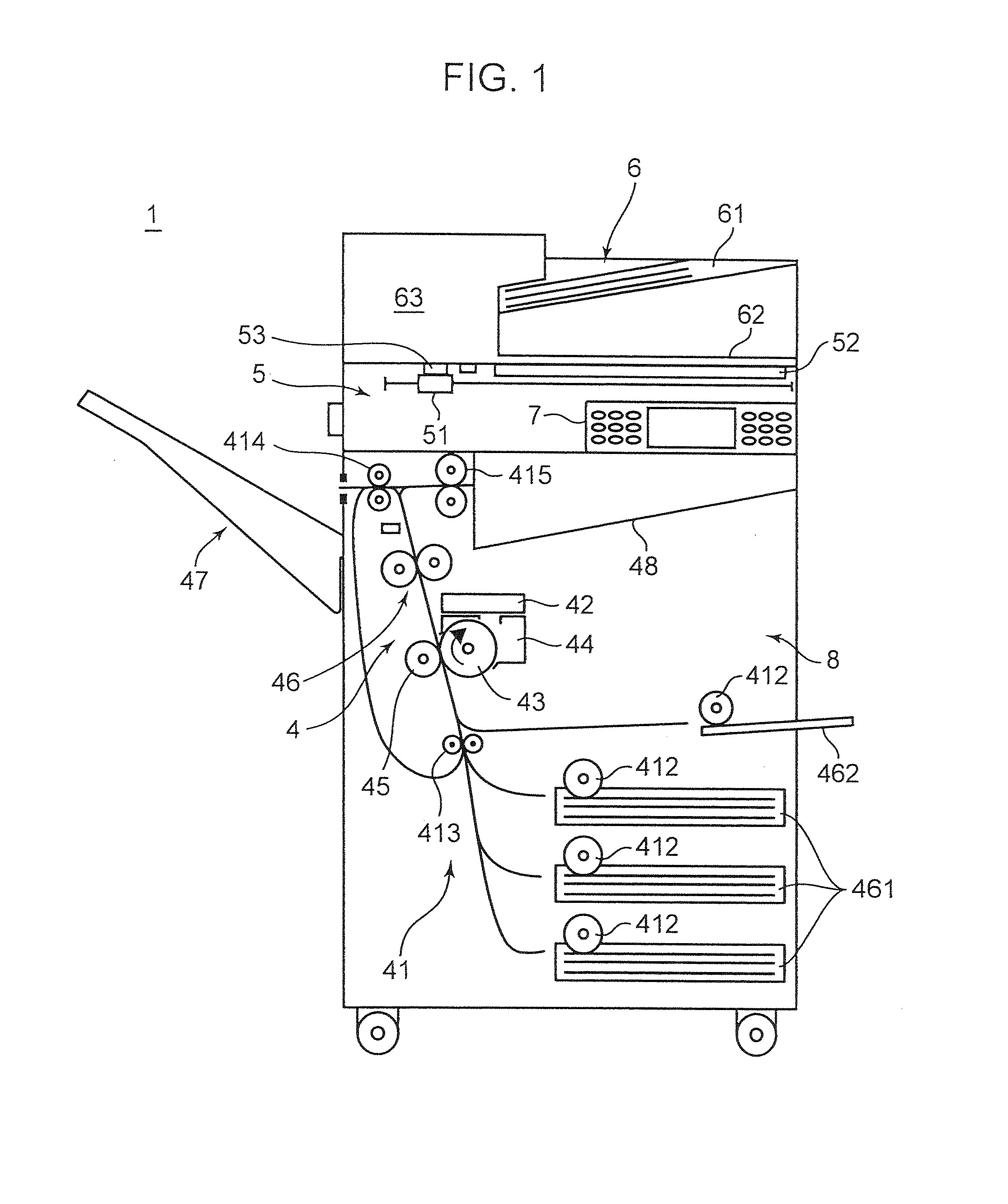
[0020]Hereinafter, an embodiment according to the present disclosure is described based on the drawings. FIG. 1 is a schematic configuration diagram of a multifunction peripheral 1 according to one embodiment of an image forming apparatus according to the present disclosure.

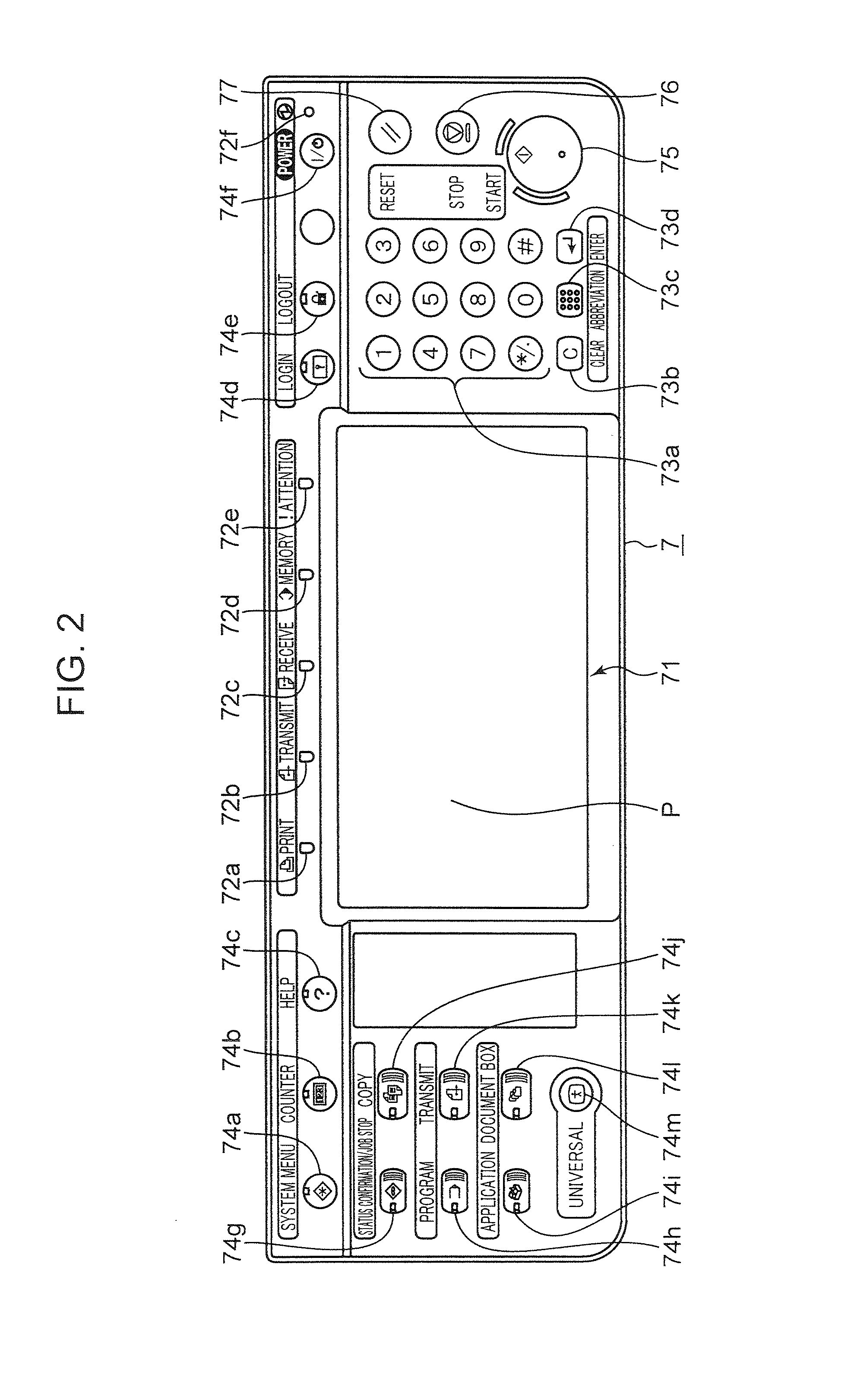
[0021]As shown in FIG. 1, the multifunction peripheral 1 includes a document reading unit 5, a document feeding unit 6, a main body unit 8 and an operation unit 7.

[0022]The document reading unit 5 is arranged atop the main body unit 8 and includes a scanner unit 51 composed of an exposure lamp, a CCD (Charge Coupled Device) and the like, a document platen 52 made of a transparent material such as glass and a document reading slit 53.

[0023]The scanning unit 51 is configured to be moved by an unillustrated driving unit. When reading a document placed on the document platen 52, the scanner unit 51 moves along a document surface at a position facing the document platen 52 and outputs obtained image data to a control ...


PUM


Abstract

An image forming apparatus includes a control unit, a login information storage, a login information receiver, a login authenticator, a target function setter, an authorization information storage, an alternative function information storage and a target function changer. The target function changer sets a user alternative function matching a user authorized function related to an authenticated user as a target function out of functions alternative to a user prohibited function and determined by alternative function information instead of the user prohibited function different from the user authorized function related to the authenticated user out of target functions when the authenticated user is set in a login state.

Description

[0001]This application is based on Japanese Patent Application Serial No. 2012-143208 filed with the Japan Patent Office on Jun. 26, 2012, the contents of which are hereby incorporated by reference.BACKGROUND[0002]The present disclosure relates to an image forming apparatus, particularly to a technology for setting a function to be executed in an image forming apparatus.[0003]Conventionally, a technology is, for example, known which registers functions permitted to be executed by each user in advance for each user registered in advance in an image forming apparatus. A technology is known which, when a user is authenticated to be an already registered user, for example, through the input of a user name and a password, sets a state where only functions, the execution of which is permitted for this user, are executable.[0004]A technology is also known which permits or denies the execution of each function based on public registration information predetermined as to whether or not to pe...

Claims


Application Information

Patent Timeline
Patent Type & Authority Applications(United States)
IPC IPC(8): G06F21/31
CPCG06F21/31G06F21/84G06F2221/2149
Inventor MAEDA, TETSUYAFUKUI, YASUHIROTSUKUDA, WATARU
Owner KYOCERA DOCUMENT SOLUTIONS INC
Why Eureka
Try Eureka