Particulate matter processing apparatus

Active Publication Date: 2014-01-02
TOYOTA JIDOSHA KK
View PDF15 Cites 1 Cited by
  • Summary
  • Abstract
  • Description
  • Claims
  • Application Information

AI Technical Summary

Benefits of technology

The present invention prevents an excessive amount of electric current from flowing to the electrode.

Problems solved by technology

In addition, the sizes of particles in the particulate matter become large, so when a filter is arranged at a downstream side, it becomes easy to trap the particulate matter with the filter.
However, electricity flows to the electrode through unburnt fuel such as HC, CO, etc., contained in an exhaust gas, too.
Then, when a lot of unburnt fuel is contained in the exhaust gas, an electric current passing through the electrode may become large, thus giving rise to a fear that a power supply, the electrode, or other circuits may be deteriorated or failed.
In addition, if the apparatus is constructed so as to withstand a large electric current, it will result in an increase in the cost of production.
Moreover, when the electric current increases, electric power consumption will become large, so there will also be a fear that fuel economy may get worse.

Method used


Image

  • Particulate matter processing apparatus
  • Particulate matter processing apparatus
  • Particulate matter processing apparatus

Examples


first embodiment

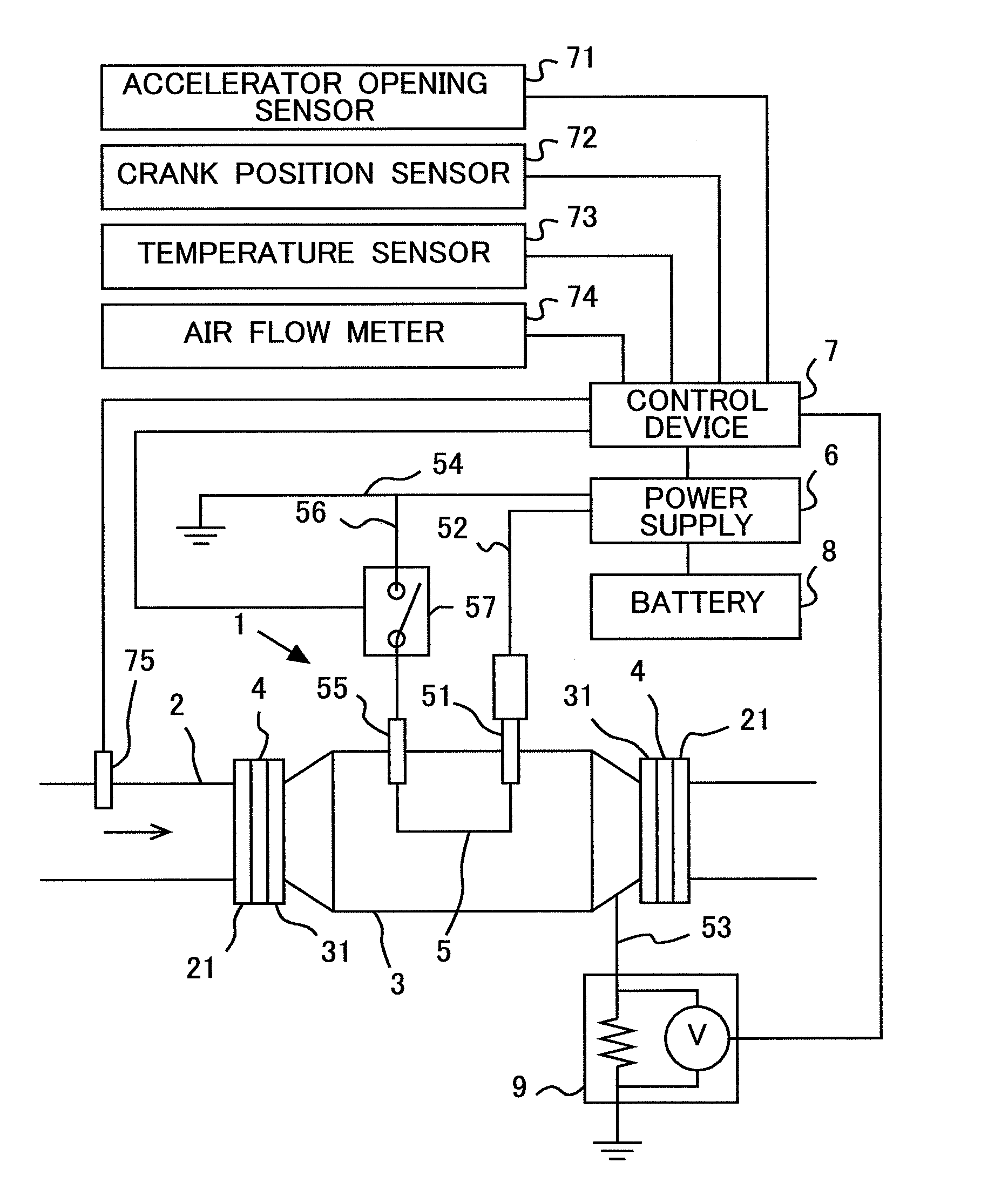
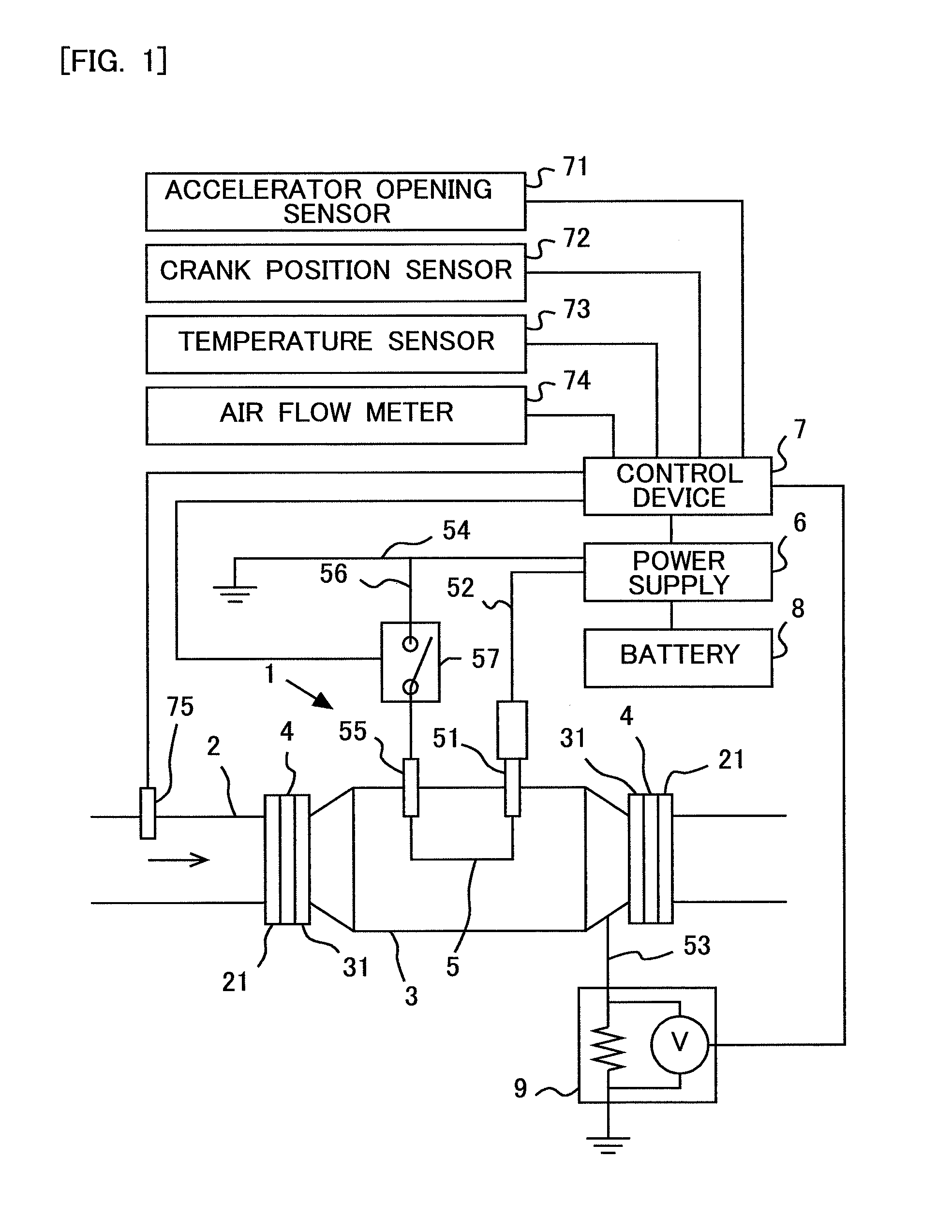
[0029]FIG. 1 is a view showing the schematic construction of a particulate matter processing apparatus 1 according to this first embodiment of the present invention. The particulate matter processing apparatus 1 is arranged in an exhaust passage 2 of a gasoline engine.

[0030]The particulate matter processing apparatus 1 is constructed to be provided with a housing 3 which is connected at its opposite ends with the exhaust passage 2. As a material for the housing 3, there is used a stainless steel material. The housing 3 is formed into a hollow cylindrical shape with its diameter being larger than that of the exhaust passage 2. The opposite end portions of the housing 3 are each formed into a tapered shape of which the cross-sectional area becomes smaller as they become closer to their end. Here, note that in FIG. 1, an exhaust gas flows through the exhaust passage 2 in the direction of an arrow, and flows into the interior of the housing 3. For this reason, the housing 3 may also be ...


PUM


Abstract

An excessively large electric current is suppressed from flowing to an electrode. Provision is made for an electrode arranged in an exhaust passage of an internal combustion engine, a power supply connected to the electrode for applying a voltage thereto, an air fuel ratio detection device for detecting or estimating an air fuel ratio of an exhaust gas which flows through the exhaust passage, and a power upper limit setting device for setting an upper limit for electric power supplied to the electrode from the power supply in cases where the air fuel ratio detected or estimate.

Description

TECHNICAL FIELD[0001]The present invention relates to a particulate matter processing apparatus.BACKGROUND ART[0002]There has been known a technique in which a discharge electrode is arranged in an exhaust passage of an internal combustion engine, and a corona discharge is caused to occur from the discharge electrode, whereby particulate matter (hereinafter also referred to as PM) is charged and condensed or aggregated (see, for example, a first patent document). By the condensation or aggregation of the particulate matter, the number of particles in the particulate matter can be decreased. In addition, the sizes of particles in the particulate matter become large, so when a filter is arranged at a downstream side, it becomes easy to trap the particulate matter with the filter.[0003]However, electricity flows to the electrode through unburnt fuel such as HC, CO, etc., contained in an exhaust gas, too. In the past, no consideration has been given to an electric current passing to the...

Claims


Application Information

Patent Timeline
IPC IPC(8): F01N3/021
CPCF01N3/021B03C3/41B03C3/49B03C3/68B03C2201/08B03C2201/24B03C2201/30B03C2201/32F01N9/00F01N11/00F01N3/01F01N2560/025F01N2900/16F01N2550/22F01N2560/07F01N2900/0601F01N2900/1411Y02T10/12Y02T10/40
Inventor MITANI, SHINICHINOMURA, HIROSHIMURASE, EIJI
Owner TOYOTA JIDOSHA KK
Why Eureka
Try Eureka