LNG fuel handling for a gas turbine engine

a gas turbine engine and fuel handling technology, applied in the direction of turbine/propulsion engine ignition, turbine/propulsion fuel heating, engine starters, etc., can solve the problem of liquid-vapor interface burning, and achieve the effect of improving engine efficiency and reducing emissions

Inactive Publication Date: 2014-01-02
ICR TURBINE ENGINE CORP
View PDF6 Cites 29 Cited by
  • Summary
  • Abstract
  • Description
  • Claims
  • Application Information

AI Technical Summary

Benefits of technology

[0007]These and other needs are addressed by the various embodiments and configurations of the present disclosure which directed generally to gas turbine engine systems and specifically to a method and apparatus to manage various fuels, especially cryogenic fuels such as LNG, to reduce emissions and to improve engine efficiency.
[0009]The vapor circuit can be controlled by the ECU which senses the vapor pressure in the LNG tank with a first pressure sensor and the combustor inlet pressure with a second pressure sensor. In the vapor circuit of this configuration, the vapor fuel control throttle valve is controlled by ECU based on the sensed pressures. Whenever ECU demands fuel, it opens the vapor fuel control throttle valve to dispense the requested amount of fuel. If the vapor pressure in the LNG tank as determined by the first pressure sensor is greater than that of the combustion chamber as determined by the second pressure sensor, fuel will flow. The liquid fuel circuit thereby provides additional fuel delivery when the ECU senses that the vapor throttle valve is wide open and still more fuel is required.
[0012]In some configurations, there is no vapor booster pump. In other configurations, a vapor booster pump can be included. The advantage of this latter configuration is that the vapor pressure can be pumped down to near atmospheric pressure. Then, when the engine is turned off, the time delay until the maximum allowable vapor pressure is reached, is maximized.

Problems solved by technology

Engines which pump or aspirate the vapor phase to the fuel injectors lower the vapor pressure and thereby cause boiling at the liquid-vapor interface.

Method used


Image

  • LNG fuel handling for a gas turbine engine
  • LNG fuel handling for a gas turbine engine
  • LNG fuel handling for a gas turbine engine

Examples


Embodiment Construction

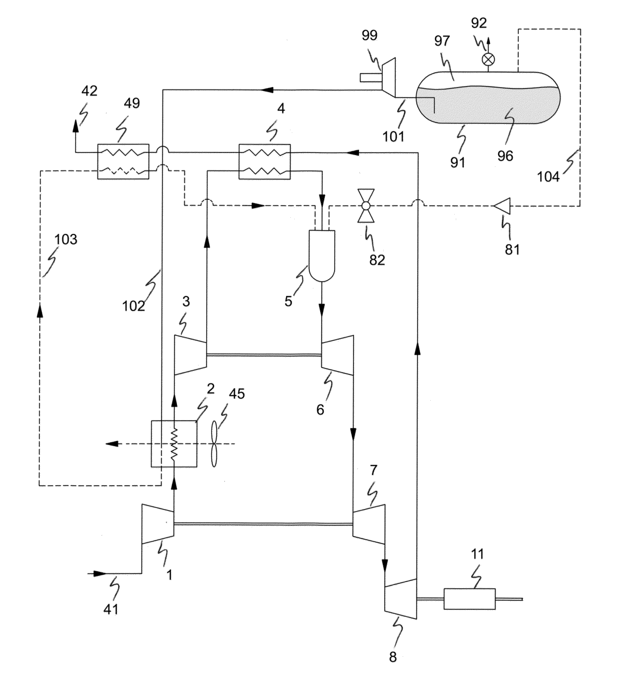
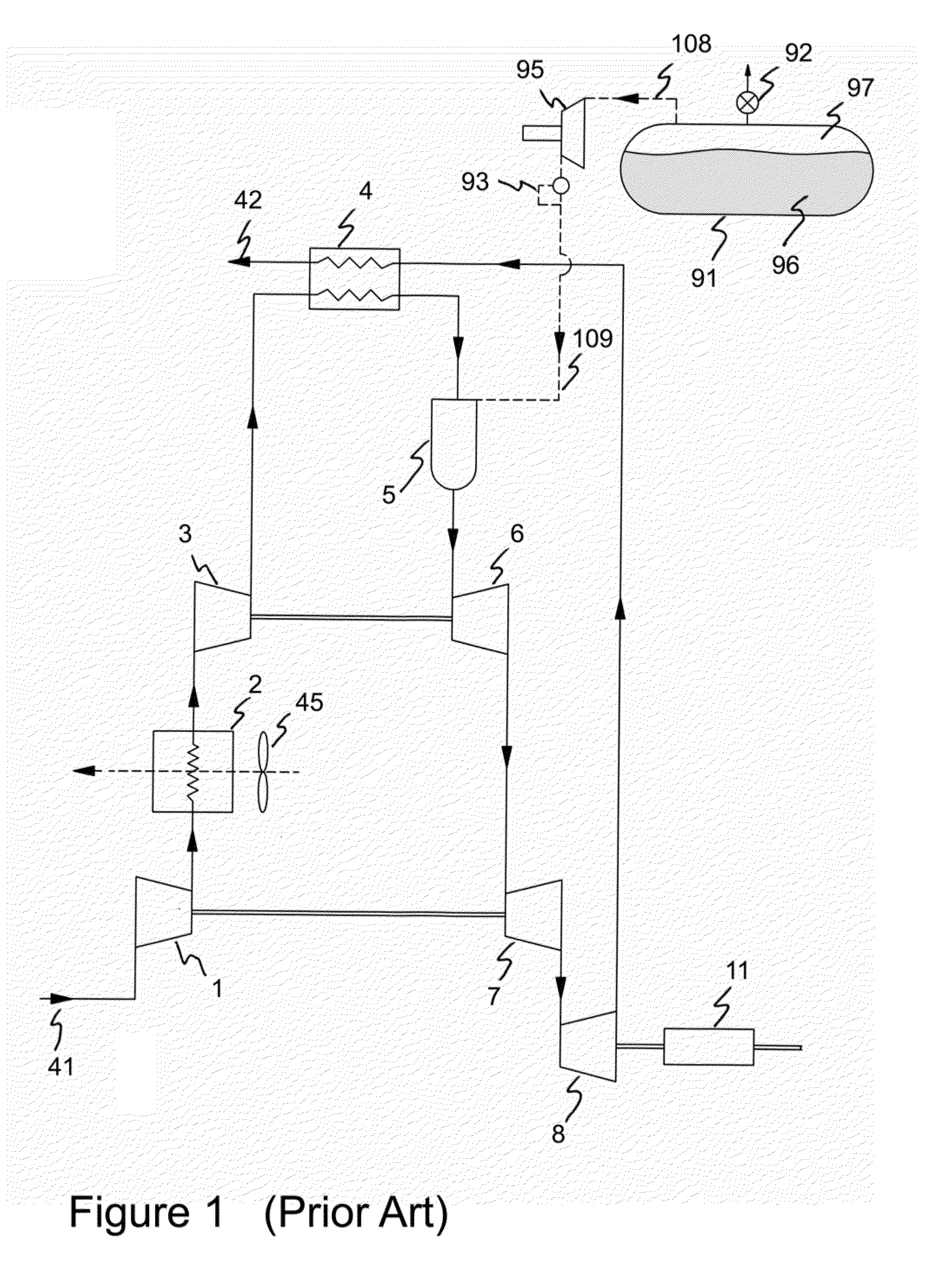
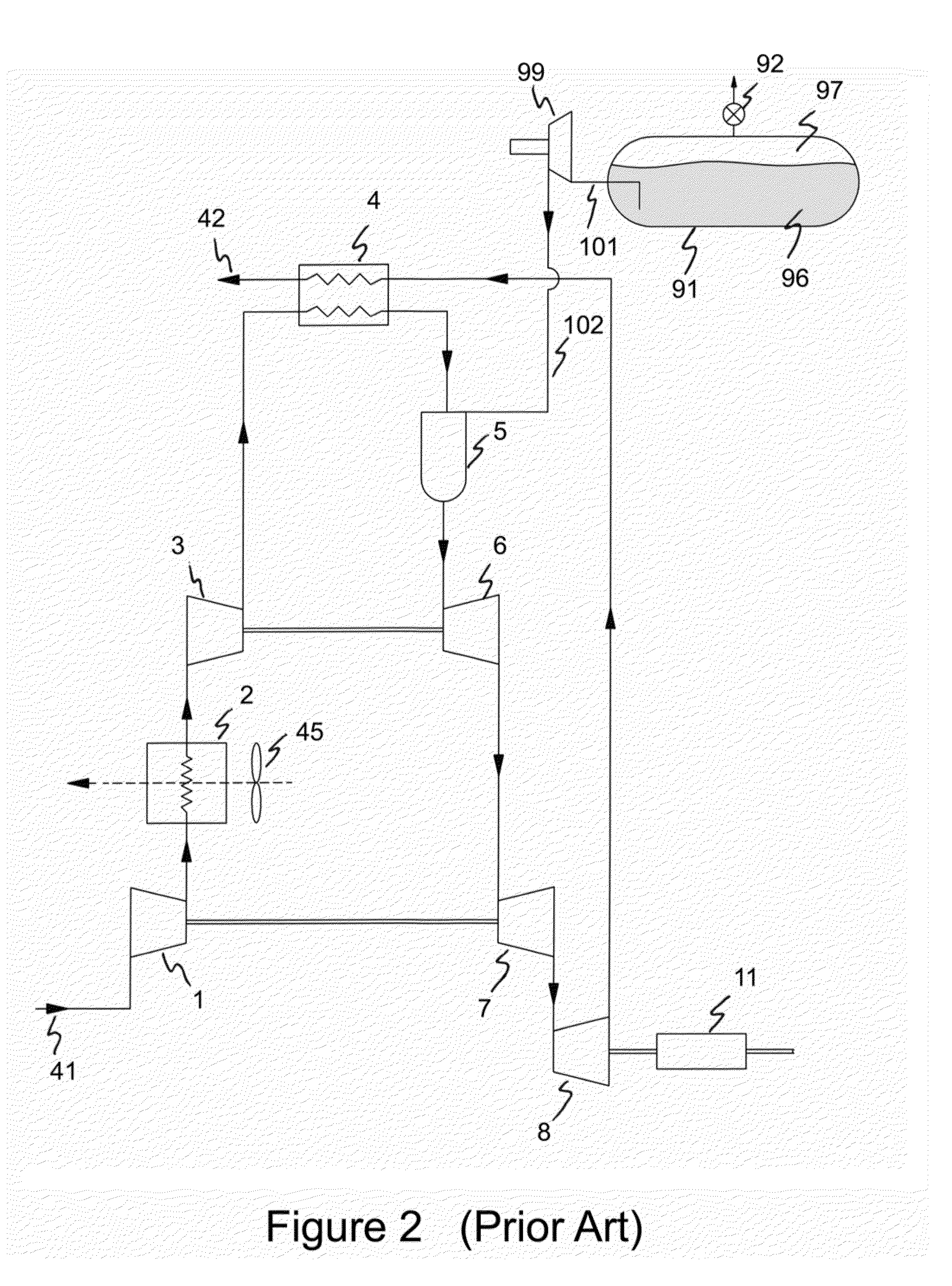
[0101]FIG. 1 is a schematic representation of a prior art LNG fuel system for injection of LNG fuel vapor into a gas turbine engine, shown here, for example, as an intercooled, recuperated gas turbine engine. The working fluid gas (typically air) for the gas turbine engine is ingested at inlet 41 into a low pressure compressor 1. The outlet of the low pressure compressor 1 passes through an intercooler 2 which removes a portion of heat from the gas stream at approximately constant pressure. The intercooler is shown with a fan 45 that blows ambient fluid, such as air or water for example, across the intercooler. Both cross-flow and counter-flow intercooler configurations may be used. The working gas then enters a high pressure compressor 3. The outlet of high pressure compressor 3 passes through a recuperator 4 where some heat from the exhaust gas is transferred, at approximately constant pressure, to the gas flow from the high pressure compressor 3. The further heated gas from recup...


PUM


Abstract

An LNG fuel system for gas turbine engine systems is disclosed that allows more efficient management of cryogenic fuels such as LNG to reduce emissions and improve engine efficiency. In one configuration, an intercooled, recuperated gas turbine engine comprises an LNG tank incorporating a liquid-to-vapor LNG fuel circuit in parallel with a vapor fuel circuit. In a second configuration, an alternate vapor fuel circuit is disclosed. In either configuration, the fuel in the liquid fuel circuit is vaporized and heated by the engine's intercooler or by both the engine's intercooler and / or a heat exchanger on the exhaust. In another configuration, both the fuel in the liquid-to-vapor LNG fuel circuit and the vapor fuel circuit are heated by a heat exchanger on the exhaust.

Description

CROSS REFERENCE TO RELATED APPLICATION[0001]The present application claims the benefits, under 35 U.S.C. §119(e), of U.S. Provisional Application Ser. No. 61 / 666,549 entitled “LNG Fuel Handling for a Gas Turbine Engine” filed Jun. 29, 2012 which is incorporated herein by reference.FIELD[0002]The present disclosure relates generally to gas turbine engine systems and specifically to methods and apparatuses to manage two phase fuels in order to reduce emissions and improve engine efficiency.BACKGROUND[0003]There is a growing requirement for alternate fuels for vehicle propulsion. These include fuels such as, for example, natural gas (both LNG and CNG), bio-diesel, ethanol, butanol, hydrogen and the like. Means of utilizing fuels needs to be accomplished more efficiently and with substantially lower carbon dioxide emissions and other air pollutants such as NOxs.[0004]The gas turbine or Brayton cycle power plant has demonstrated many attractive features which make it a candidate for adva...

Claims


Application Information

Patent Timeline
Patent Type & Authority Applications(United States)
IPC IPC(8): F02C7/22
CPCF02C7/22F02C3/22F02C7/224Y02T50/60
Inventor KESSELI, JAMES B.DONNELLY, FRANK WEGNER
Owner ICR TURBINE ENGINE CORP
Why Eureka
Try Eureka