Self-suspending proppants for hydraulic fracturing

a hydraulic fracturing and self-suspension technology, applied in the field of systems, formulations and methods of fracturing technologies, can solve the problems of high dose rate of expensive polymer, production equipment, and inability to highly effective viscosifiers and suspending agents, and achieve the effect of reducing the amount of thickening agents

Inactive Publication Date: 2014-01-02
SELF SUSPENDING PROPPANT
View PDF5 Cites 104 Cited by
  • Summary
  • Abstract
  • Description
  • Claims
  • Application Information

AI Technical Summary

Benefits of technology

[0031]In a process for fracturing a geological formation penetrated by a well in which a fracing fluid containing a proppant is charged into the geological formation with pulsed pressure, the invention includes a method for reducing the amount of thickening agent that is added to the fracing fluid comprising selecting as the proppant the modified proppant of the invention. The modified proppants of the invention preferably hydrate essentially completely within 2 hours, such as within 10 minutes, of first being combined with the fracing fluid.

Problems solved by technology

This process results in cracks and breaks that disrupt the underlying layer to allow the hydrocarbon product to be carried to the well bore at a significantly higher rate.
While these polymers are effective as friction reducers, they are not highly effective as viscosifiers and suspending agents.
The linear gel and crosslinked gel fluids have certain advantages but they require a high dose rate of expensive polymer.
If changes within the reservoir during well production force the proppants out of position, production equipment can be damaged, and the conductivity of the reservoir formation can be decreased as the reservoir pores are plugged by the displaced proppants.
Care must be taken that the proppants do not fail under this stress, lest they be crushed into fine particles that can migrate to undesirable locations within the well, thereby affecting production.
The high pressures and temperatures combine with the chemicals used in frac fluids can adversely affect the proppant particles, resulting in their diagenesis, which can eventually produce fine particulate matter that can scale out and decrease the productivity of the well over time.
Resins, though, can decrease the conductivity and permeability of the fracture, even as the proppants are holding it open.
Also, resins can fail, so that their advantages are lost.
Resin-based systems tend to be expensive and they are still prone to settling out of suspension.
In addition, there are health, safety and environmental concerns associated with the handling and processing of proppants.
With chronic exposure, this dust can be harmful to workers, resulting in various inhalation-associated conditions such as silicosis, chronic obstructive pulmonary disease, lung cancers in the like.
In addition to these health effects, the fines can cause “nuisance dust” problems such as fouling of equipment and contamination of the environment.
The additives, though, can affect the rheological properties of the transport slurry, making it more difficult to deliver the proppants to the desired locations within the fracture.
In addition, the use of additives can interfere with uniform placement of the proppant mixture into the fracture site.
While there are known methods in the art for addressing the limitations of proppant systems, certain problems remain.

Method used


Image

  • Self-suspending proppants for hydraulic fracturing
  • Self-suspending proppants for hydraulic fracturing
  • Self-suspending proppants for hydraulic fracturing

Examples


example 1

Preparation of Inner Polymer Layer

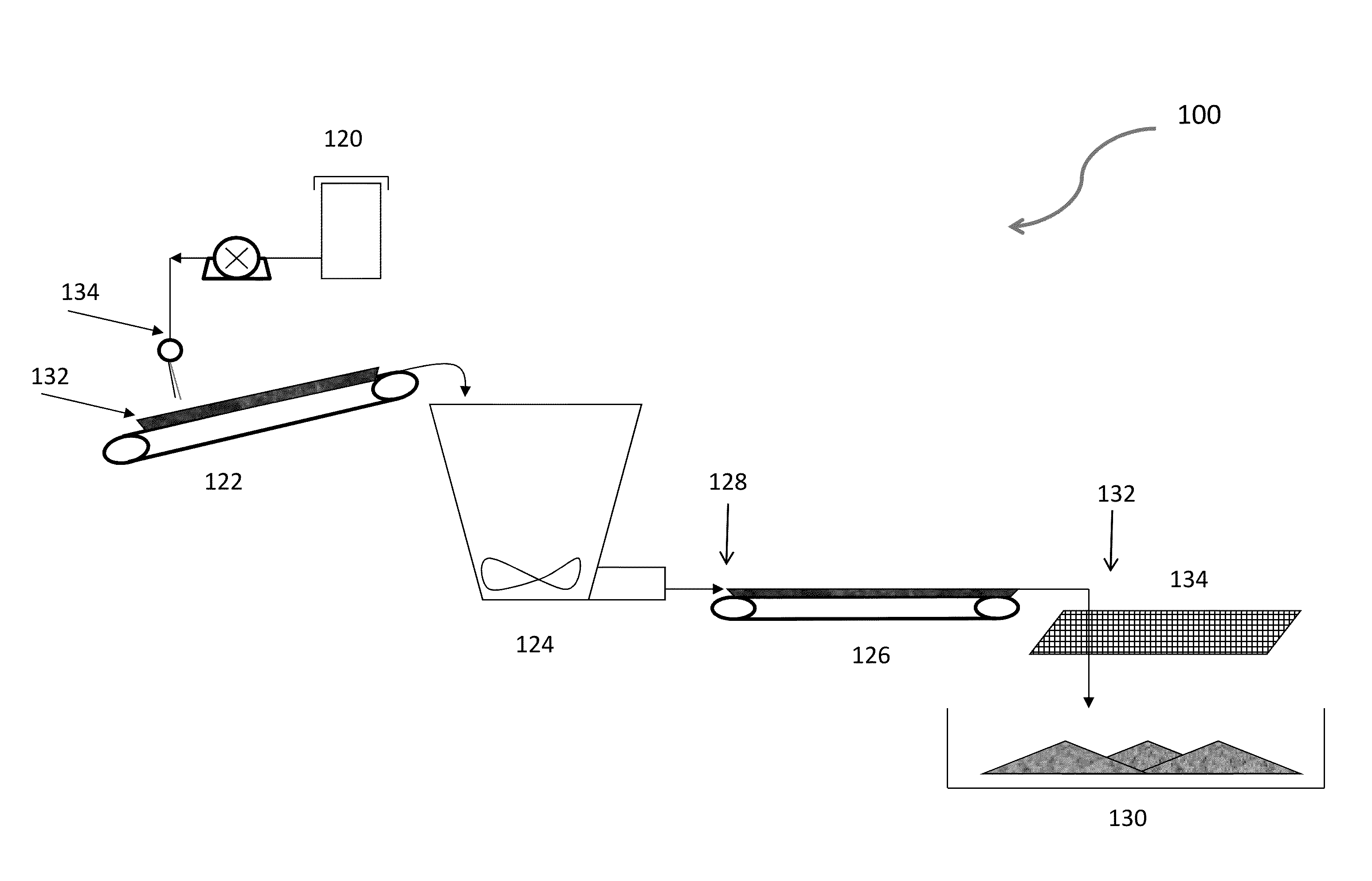
[0166]An inner polymer layer of 100 ppm concentration was prepared on a sand sample by adding 200 g 30 / 70 mesh frac sand to a FlackTek Max 100 long jar. To the sand was added 85 g tap water and 2 g of a 1% polydiallyldimethylammonium chloride (PDAC) solution. The sample was then shaken by hand for approximately 5 minutes, vacuum filtered and dried in an oven at 80° C. The sand sample was then removed from the oven and used in subsequent testing.

[0167]An identical method was used as described above to formulate a 10 ppm inner polymer layer coating with the exception being that only 0.2 g of a 1% PDAC solution were used.

[0168]An identical method was used as described above to formulate an inner polymer layer at a maximum polymer loading (“Max PDAC”) with the exception that 1 g of a 20 wt % PDAC solution was used. Following treatment the sand was washed with excess tap water, vacuum filtered and dried in an oven at 80° C. The sand sample was then remov...

example 2

Preparation of Inner Polymer Layer

[0169]An inner polymer layer of 100 ppm concentration was prepared on a sand sample by dissolving 0.2 g LPEI 500 in 10 g ethanol to form a 2% LPEI 500 solution in ethanol. To 70 g ethanol in a 250 mL round bottom flask was added 0.75 g of the 2% LPEI 500 solution. Then 150 g of 30 / 70 mesh frac sand was added to the round bottom flask. The solvent was removed using a rotary evaporator with a 65° C. water bath. The sample was then removed from the flask and used in subsequent testing.

example 3

Preparation of Outer Polymer Layer

[0170]Outer polymer layers were applied to sand samples by mixing sand with liquid Flopam EM533 polymer under different conditions. In one coating method, polymer product was added neat. In another coating method the polymer product was extended by diluting with hexane. For hexane dilution 10 g polymer was added to 10 g hexane in a 40 mL glass vial and vortex mixed until homogenous. Polymer was then added to 30 / 70 mesh frac sand samples of 30 g in FlackTek Max 100 jars. Samples were placed in a FlackTek DAC150 SpeedMixer at 2600 rpm for about 25 seconds. Samples were removed from SpeedMixer and allowed to dry in an oven at 80° C. overnight.


PUM

PropertyMeasurementUnit
weight average molecular weightaaaaaaaaaa
thicknessaaaaaaaaaa
thicknessaaaaaaaaaa

Abstract

The invention provides for modified proppants, comprising a proppant particle and a hydrogel coating, wherein the hydrogel coating localizes on the surface of the proppant particle to produce the modified proppant, methods of manufacturing such proppants and methods of use.

Description

RELATED APPLICATIONS[0001]This application claims the benefit of Provisional Application Ser. No. 61 / 662,681, filed Jun. 21, 2012, U.S. Provisional Application Ser. No. 61 / 725,751, filed Nov. 13, 2012, U.S. Provisional Application Ser. No. 61 / 764,792, filed Feb. 14, 2013, U.S. Non-provisional application Ser. No. 13 / 599,828, field Aug. 30, 2012, and U.S. Non-provisional application Ser. No. 13 / 838,806, field Mar. 13, 2013 (Ser. No. 13 / 599,828 and Ser. No. 13 / 838,806 additionally claiming the benefit of U.S. Provisional Application Ser. No. 61 / 529,600, filed Aug. 31, 2011, and U.S. Provisional Application Ser. No. 61 / 635,612, filed Apr. 19, 2012). The entire contents of all of the above-referenced applications are incorporated by reference herein.FIELD OF APPLICATION[0002]This application relates generally to systems, formulations and methods for fracturing technologies.BACKGROUND[0003]In the process of acquiring oil and / or gas from a well, it is often necessary to stimulate the flow...

Claims


Application Information

Patent Timeline
Patent Type & Authority Applications(United States)
IPC IPC(8): C09K8/80E21B43/267
CPCC09K8/805E21B43/267C09K2208/24C09K2208/26C09K8/62Y10T428/2998Y10T428/2991C09K8/80
Inventor MAHONEY, ROBERT P.SOANE, DAVID S.HERING, MARIE K.KINCAID, KEVIN K.PORTILLA, ROSA CASADOWUTHRIDGE, PHILIP
Owner SELF SUSPENDING PROPPANT
Why Eureka
Try Eureka