Valve current control method based on modular multi-level converter

a multi-level converter and control method technology, applied in the direction of dc-ac conversion without reversal, power conversion systems, electrical equipment, etc., can solve the problems of system instability, increase the loss of the valve, and distortion of the actual valve current, and achieve good output characteristics

Inactive Publication Date: 2014-01-02
STATE GRID CORP OF CHINA +1
View PDF3 Cites 37 Cited by
  • Summary
  • Abstract
  • Description
  • Claims
  • Application Information

AI Technical Summary

Benefits of technology

[0019]The invention provides a valve current control method based on modular multi-level converter, this method not only can realize stability of the dynamic performance of the system

Problems solved by technology

This causes the distortion of the actual valve current, and this distortion not only could increase loss of the valve, but also could cause system instable.
But this method can't achieve no error control in double frequency components, and in high voltage applications, it is not economical to suppress double frequency components by increasing arms reactance value.
However, the method is only applicable to steady operation state, because under abnormal condition, converter three-phase transmitted powers differ, so the circulating current control method can't achieve good control effect.
At the same time, because each phase unit adopts capacitor and inductor in series form, so it is likely to resonate of each unit, and cause poor dynamic performance.
These are practi

Method used


Image

  • Valve current control method based on modular multi-level converter
  • Valve current control method based on modular multi-level converter
  • Valve current control method based on modular multi-level converter

Examples


Embodiment Construction

[0042]The detail of the embodiments is described as below incorporated with the figures by way of cross-reference for the present invention.

[0043]The valve current control of modular multi-level converter can be divided into the low frequency oscillation current control and the double frequency harmonic component control two control layers, these control schemes are different. The following will introduce the low-frequency oscillation current control and the double frequency harmonic component control.

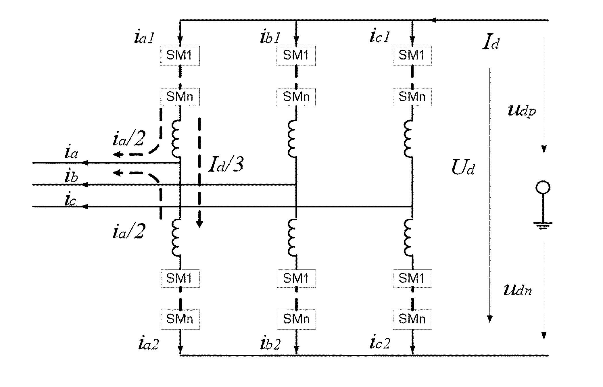
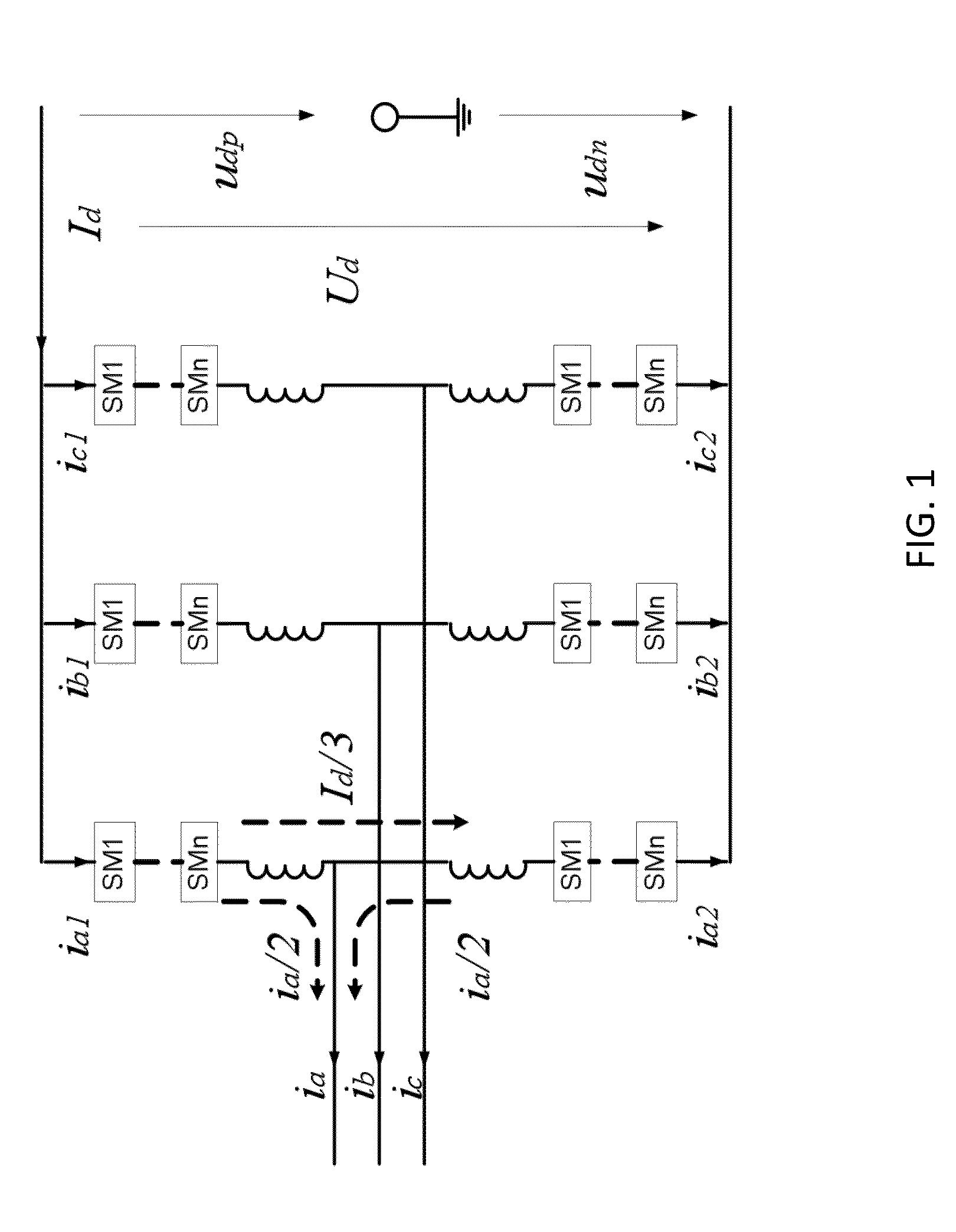
[0044]1. For low frequency oscillations of the current, the control can be divided into oscillation circulating current control among arms and that between two converters.

[0045](1) the oscillation circulating current control steps of among arms is as following:

[0046]FIG. 3 is the schematic diagram of calculation method of arm circulation. As FIG. 3 shown, first add the upper arm valve current and the lower arm valve current, and then divided by 2, and got the actual value of the DC cur...


PUM


Abstract

The present invention relates to valve current control method based on modular multi-level converter, this method includes the control of the low frequency oscillations of the current and that of double frequency harmonic component; For said low frequency oscillations of the current, the control method includes some steps as below: first, calculate the half of the sum of the upper arm current and the lower arm current, it is the valve DC current component, said DC current component is arm circulating current; Secondly, comparing the actual value of the arm circulating current to setting value of that, the error is obtained, after some signal processing, additional output set voltage is obtained. For said the double frequency harmonic component of current, the control method includes some steps as below: firstly, figure out capacitor voltage fluctuation prediction value of the sub module; secondly, the output voltage is divided by the sum of the sub module reference voltage and the capacitor voltage fluctuation prediction value, and get the actual output set number of sub module. This method not only can realize stability of the dynamic performance of the system, but also can suppress the arm double frequency harmonic component, at the same time under the abnormal conditions of the AC system; the valve current has good output characteristics.

Description

RELATED APPLICATIONS[0001]This application is a United States National Stage Application filed under 35 U.S.C 371 of PCT Patent Application Ser. No. PCT / CN2011 / 001814, filed Oct. 31, 2011, which claims the benefit of Chinese Patent Application Serial No. 201110063053.4, filed on Mar. 16, 2011, the disclosure of all of which are hereby incorporated by reference in their entirety.FIELD OF THE INVENTION[0002]The invention relates to flexible direct current transmission (VSC-HDVC) filed and its control method, in particular, relates to a valve current control method based on modular multi-level converter.BACKGROUND OF THE INVENTION[0003]Because of the flexible application performance of VSC-HVDC, it exhibits very broad application prospects in city power grid interconnection, the new energy gird and passive load power supply and other fields. And the modular multi-level converter, which is in last few years converter of arisen a converter, is fit for high voltage flexible direct current...

Claims


Application Information

Patent Timeline
IPC IPC(8): H02M7/44
CPCH02M7/44H02M1/14H02M7/483H02M1/0003H02M7/4835
Inventor TANG, GUANGFUYANG, JIEWANG, SHANSHANKONG, MINGLIU, DONG
Owner STATE GRID CORP OF CHINA
Why Eureka
Try Eureka