Anti-Reflection Coat and Optical Device

a technology of anti-reflection coat and optical device, which is applied in the direction of coating, instruments, nanotechnology, etc., can solve the problems of difficult to achieve a further lower refractive index of film formed by vapor deposition method, difficult to accurately form an anti-reflection coat on the surface of a lens having a large curvature, and a curvature. , to achieve the effect of excellent durability and stability, excellent appearance, and excellent durability

Active Publication Date: 2014-01-09
TAMRON
View PDF6 Cites 26 Cited by
  • Summary
  • Abstract
  • Description
  • Claims
  • Application Information

AI Technical Summary

Benefits of technology

[0013]So, an object of the present invention is to provide an anti-reflection coat in which a low refractive index layer is excellent in film formability, adhesion and durability; and having excellent antireflection performance and an optical device.
[0023]In the present invention, the surface of the intermediate layer is preferably subjected to a surface treatment for improving the wettability to the coating liquid.
[0029]According to the present invention, the low refractive index layer is formed well on the surface of the intermediate layer by a wet film formation method and the low refractive index layer adheres well to the substrate via the intermediate layer because the intermediate layer which has wettability to the coating liquid used when the low refractive index layer is formed and is mainly composed of an organometallic compound which adheres well to the binder is provided on the substrate. Further, the hollow silica particles which adheres well to the intermediate layer via the binder, and hence the detachment or the like of the low refractive index layer caused by the dropout of the hollow silica particles or the like is prevented, and an anti-reflection coat having excellent appearance can be manufactured. Next, the hollow silica particle constituting the low refractive index layer is a material excellent in durability and stability, and hence the durability and the stability of the anti-reflection coat are made excellent. Moreover, the anti-reflection coat according to the present invention exhibits excellent antireflection performance for the light beam in a wide wavelength band and a wide incident angle range because the interface-reflected light occurring at the interface between the individual layers or the interface with the substrate is utilized.

Problems solved by technology

However, such an optical design can assure the low reflectance only in a narrow band (in the vicinity of the reference wavelength).
However, as the materials which can be used in the vapor deposition method for film formation are limited, it has been difficult to achieve a further lower refractive index in a film formed by using a vapor deposition method.
However, the wet film formation method is hard to accurately form an anti-reflection coat on the surface of a lens, a curving surface.
In particular, it is extremely difficult to accurately form an extremely thin anti-reflection coat on the surface of a lens having a large curvature.
When surface defect such as micro-protrusions due to foreign matter or micro-recesses due to flaws on the surface of a lens exist, the unevenness in the film thickness generates over wide area from such defect sites.
Consequently, the anti-reflection coat may have large quality deviation, poor antireflection performance or poor appearance.
So, the higher the void fraction in the layer, the lower the refractive index but the more poor in the durability at the same time.
As described above, as the refractive index and the durability are in a trade-off relation; it is difficult to achieve excellent antireflection performance because refractive index of the layer cannot be largely decreased to obtain a practically sufficient durability.
Moreover, in the anti-reflection coat disclosed in Patent Document 1, adhesion of the low refractive index layer to the substrate is not sufficiently investigated, and adhesion of the low refractive index layer to the substrate may be low.
However, as the hard coat layer is formed by a wet film formation method also, the hard coat layer uniform in thickness may hardly be formed on a lens having a large curvature.
So, the anti-reflection coat disclosed in Patent Document 1 is equal to a single-layered optical interference layer, and as described above, when the wavelength of the incident light deviates from the design wavelength, or when the incident angle range of the incident light extends over a wide range, a problem such that no sufficient antireflection performance is achieved in the anti-reflection coat may arise.
That is, when a porous silica aerogel layer will be formed on the surface of a SiO2 layer to have a refractive index of 1.15 as a dense layer, no practical durability is obtained due to the original property of silica aerogel.

Method used


Image

  • Anti-Reflection Coat and Optical Device
  • Anti-Reflection Coat and Optical Device
  • Anti-Reflection Coat and Optical Device

Examples


example 1

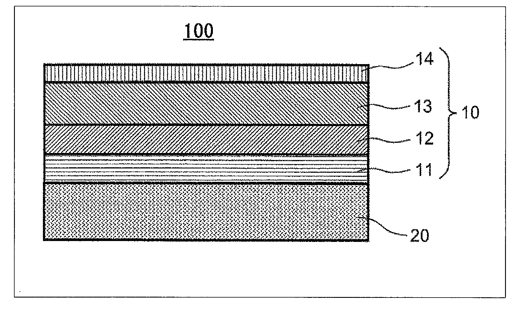
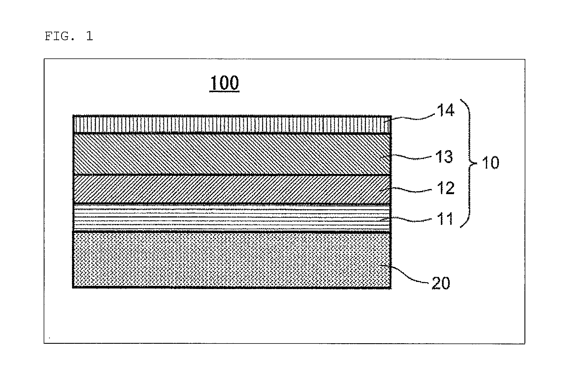
[0098]In Example 1, a lens (refractive index n=1.86) made of optical glass FDS90 manufactured by HOYA Corp. was used as the substrate 20. On the surface of the substrate 20, an anti-reflection coat 10 having a multilayer structure shown in Table 1 was provided. Specifically, the anti-reflection coat 10 was prepared as follows. First, an inorganic base layer 11 was formed on the surface of the substrate 20 by using the ARES 1510 manufactured by Leybold Optics GmbH according to a vacuum vapor deposition method. As shown in Table 1, the inorganic base layer 11 was made to have a two-layer structure by sequentially stacking an extremely thin film of Al2O3 (refractive index n=1.63) and an extremely thin film of SiO2 (n=1.48) on the surface of the substrate 20. The thicknesses of the layers constituting the inorganic base layer 11 are as shown in Table 1. In the present specification, a just “SiO2” is general silica without hollow structure.

[0099]By the way, an intermediate layer 12 compo...

example 2

[0101]In Example 2, an intermediate layer 12 composed of an organosilicon oxide film was formed by using tetramethylsilane (TMS). Layer structure of the anti-reflection coat 10 and thickness of each layer were set as shown in Table 2. The inorganic base layer 11 and the low refractive index layer 13 were each formed in almost the same manner as in Example 1, and the intermediate layer 12 was formed as follows.

[0102]By the way, in the formation of the intermediate layer 12, an organosilicon oxide film can be deposited on the surface of the inorganic base layer 11 in almost the same manner as in Example 1 except that tetramethylsilane is used as the thin film-constituting raw material. In the process, the refractive index of the prepared organosilicon oxide film can be appropriately managed within a range from 1.40 to 1.65, by arranging the gas flow rates and the discharge conditions within a flow rate range of the tetramethylsilane gas introduced into the chamber from 10 sccm to 200 ...

example 3

[0103]In Example 3, an anti-reflection coat 10 was prepared in the same manner as in Example 1 except that layer structure and thickness of each layer were set as shown in Table 3.

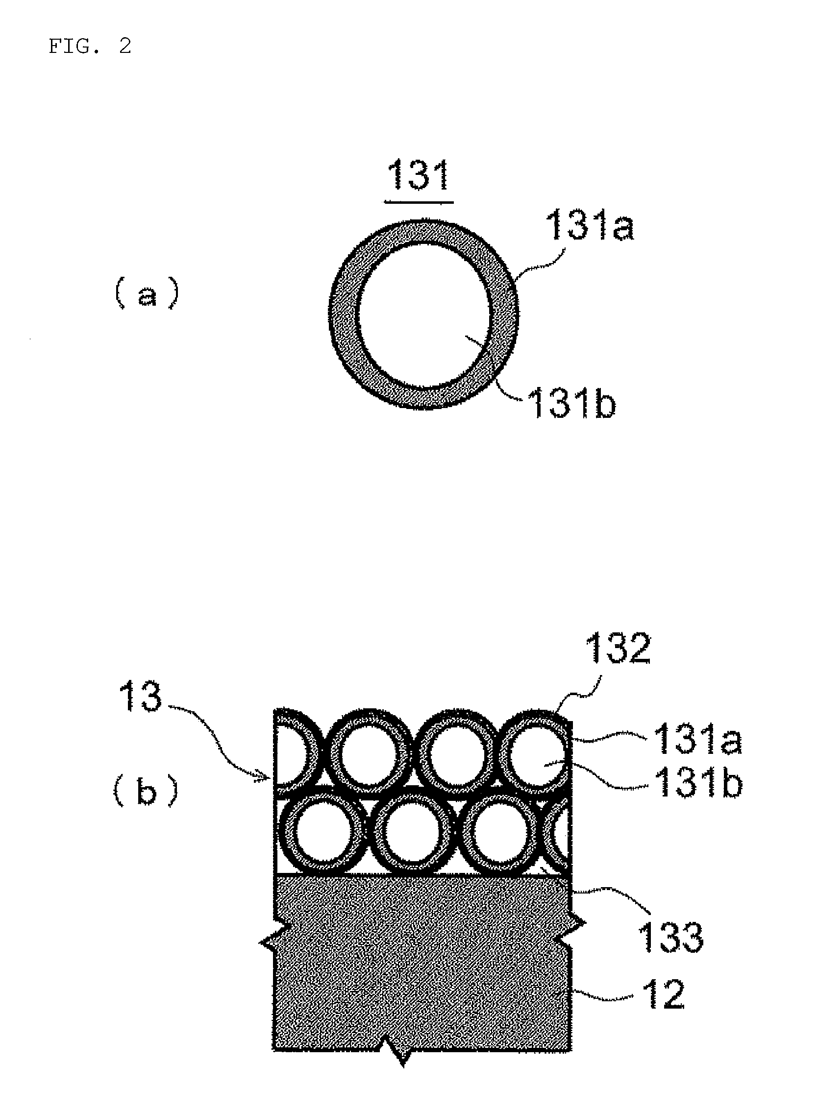
TABLE 3RefractivePhysical filmMaterialindexthickness (nm)substrateFDS901.86—InorganicAl2O31.6311base layerTiO2 + ZrO22.1029Al2O31.6330TiO2 + ZrO22.1031Al2O31.6371TiO2 + ZrO22.103SiO21.4835IntermediateOrganosilicon1.541layeroxide (HMDSO)LowHollow silica1.20104refractiveparticle + acrylicindex layerresin


PUM

PropertyMeasurementUnit
refractive indexaaaaaaaaaa
particle sizeaaaaaaaaaa

Abstract

An anti-reflection coat includes an intermediate layer and a low refractive index layer sequentially stacked on a substrate, and preventing the reflection of incident light by optical interference effect, wherein the low refractive index layer is a film formed on the surface of the intermediate layer by a wet film formation method using a coating liquid including layer-constituting raw materials which includes hollow silica particles adhering each other with a binder, and the intermediate layer is a layer mainly composed of an organometallic compound which adheres well to the binder and having wettability to the coating liquid; and provides an optical device including the anti-reflection coat.

Description

BACKGROUND OF THE INVENTION[0001]1. Field of the Invention[0002]The present invention relates to an anti-reflection coat preventing the reflection of incident light by utilizing optical interference effect and an optical device provided with the anti-reflection coat.[0003]2. Background Art[0004]On the surface of the substrate of an optical device such as a lens or a prism constituting an optical apparatus, an anti-reflection coat is provided to enhance the optical transmittance. The anti-reflection coat reduces the reflection of incident light mainly utilizing optical interference effect. In an anti-reflection coat composed of a single layer, part of the incident light reflects at both the surface of the anti-reflection coat and the interface between the anti-reflection coat and the substrate. When the optical film thickness of the anti-reflection coat is quarter of the incident light wavelength (Lambda), the phase of the interface-reflected light is reversed in relation to the phas...

Claims


Application Information

Patent Timeline
Patent Type & Authority Applications(United States)
IPC IPC(8): G02B1/11B32B7/02G02B1/111G02B1/14
CPCG02B1/111Y10S977/755B82Y20/00
Inventor SHIBUYA, MINORUYAMASHITA, NAOKI
Owner TAMRON
Why Eureka
Try Eureka