

SYSTEM USING SELECTIVE CATALYTIC REDUCTION FOR IMPROVING LOW-TEMPERATURE De-NOx EFFICIENCY AND REDUCING YELLOW PLUME
a catalytic reduction and low-temperature technology, applied in the direction of lighting and heating apparatus, separation processes, emission prevention, etc., can solve the problems of increasing the amount of catalyst, increasing the efficiency of the de-no/sub>catalytic at low temperature, and requiring a lot of cost, so as to reduce the volume of the catalytic reactor, the effect of increasing the catalyst and reducing the cost of auxiliary fuel
Active Publication Date: 2014-01-09
GSCO
View PDF1 Cites 23 Cited by
- Summary
- Abstract
- Description
- Claims
- Application Information
AI Technical Summary
Benefits of technology
The patent describes a method to effectively remove NOx from exhaust gas at low temperatures without increasing the amount of catalyst. This is achieved by adding an oxidation catalyst or an ozone generator to an existing selective catalytic reduction (SCR) facility. This can result in significantly lower operation costs and reduced catalytic reactor volume. Additionally, the method can minimize the SCR reaction temperature and reduce auxiliary fuel cost when applied to incinerators or glass melting furnaces. Furthermore, the method can easily remove yellow plume produced during startup of combined cycle power plants using the existing SCR facility.
Problems solved by technology
Nitrogen oxides (NOx) emitted from power station boilers, gas turbines, industrial boilers, incinerators, diesel engines, or the like are a major cause of pollution.
However, to increase the amount of the de-NOx catalyst requires additional cost since operation of a blower is necessary because of poor combustion status owing to increased reactor volume and pressure drop.
And, to improve the efficiency of the de-NOx catalyst at low temperature is technically very difficult and requires a lot of cost.
Meanwhile, combined cycle power plants produce yellow plume during startup of gas turbines because a large quantity of NO2 is emitted.
However, removal using a catalyst is not easy because of low temperature of the exhaust gas and slow rate of the following reaction.
However, this method is problematic in that carcinogenic formaldehyde is produced, operation cost increases due to the expensive ethanol and a selective catalytic reduction (SCR) process has to be added since NO, which is produced during normal operation of the gas turbine, is not removed
Although the non-thermal plasma or ozone generator is very useful in that it can be used at low temperature and the degree of NO oxidation can be easily controlled electrically, it is less economical as compared to heating of the exhaust gas to the optimum temperature necessary to achieve the desired reaction efficiency using, for example, a duct burner, at present.
Method used
View moreImage
Smart ImageViewing Examples

Examples
example
[0055]Fast selective catalytic reduction (SCR) was carried out under the following condition.
[0056]De-NOx efficiency was measured under the condition of NH3 / NOx=1.0, O2=3%, H2O=6%, SV=60,000 hr−1 and temperature=180-300° C., with NOx concentration fixed at 300 ppm and NO2 / NOx ratios of 0.1, 0.2, 0.3 and 0.4.
TABLE 1NO2 / NOxNO (ppm)NO2 (ppm)NOx (ppm)0.1270303000.2236643000.3212883000.4174126300
[0057]As seen from FIG. 10, the de-NOx efficiency increased with the NO2 / NOx ratio. FIG. 11 shows a relationship between the NO2 / NOx ratio and temperature when de-NOx efficiency is 80%. The reaction temperature could be lowered by as much as 80° C., from 273° C. when NO2 / NOx=0.1 to 194° C. when NO2 / NOx=0.4.
Login to View More PUM
| Property | Measurement | Unit |
|---|---|---|
| Temperature | aaaaa | aaaaa |
| Temperature | aaaaa | aaaaa |
| Efficiency | aaaaa | aaaaa |
Abstract
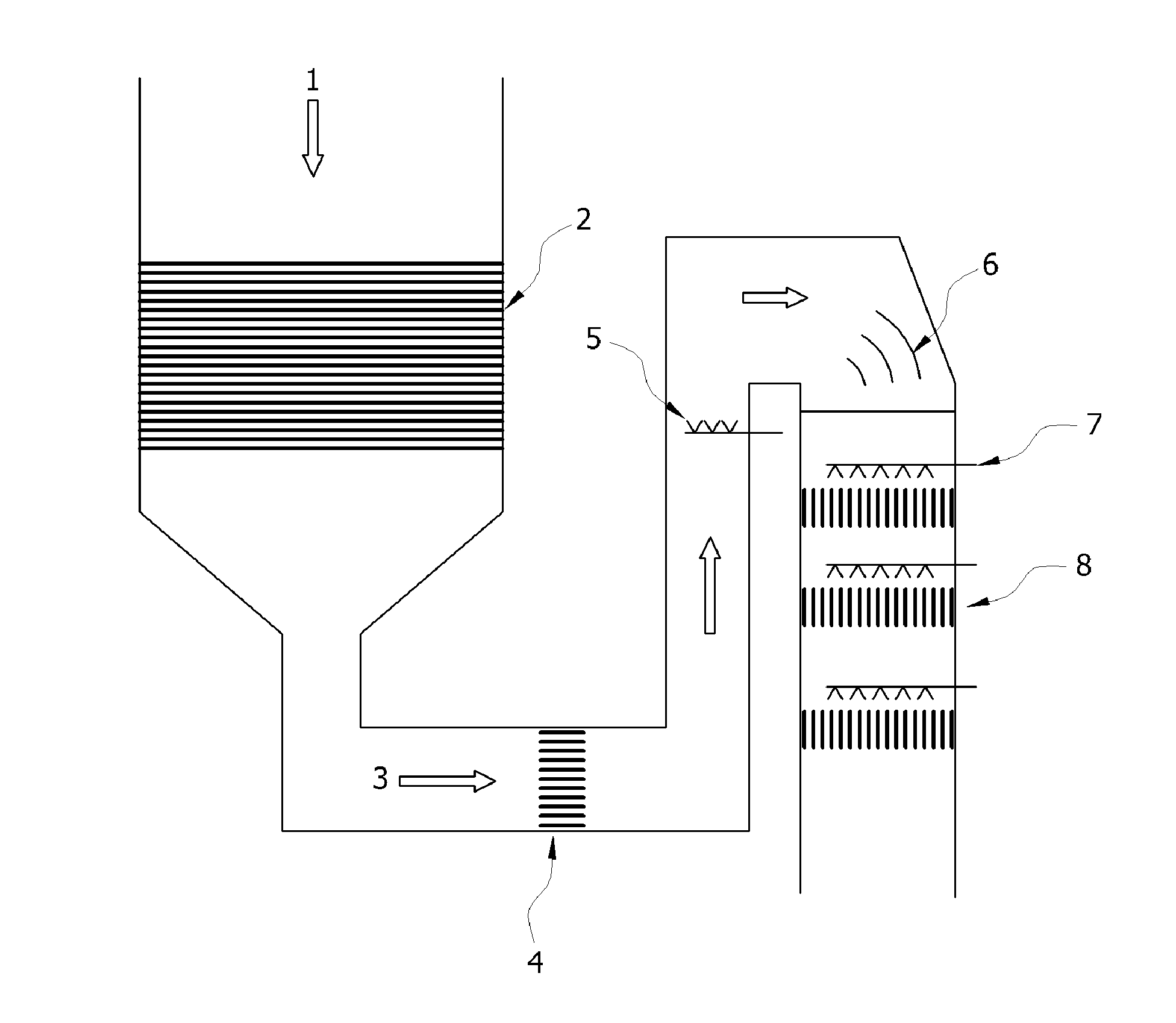
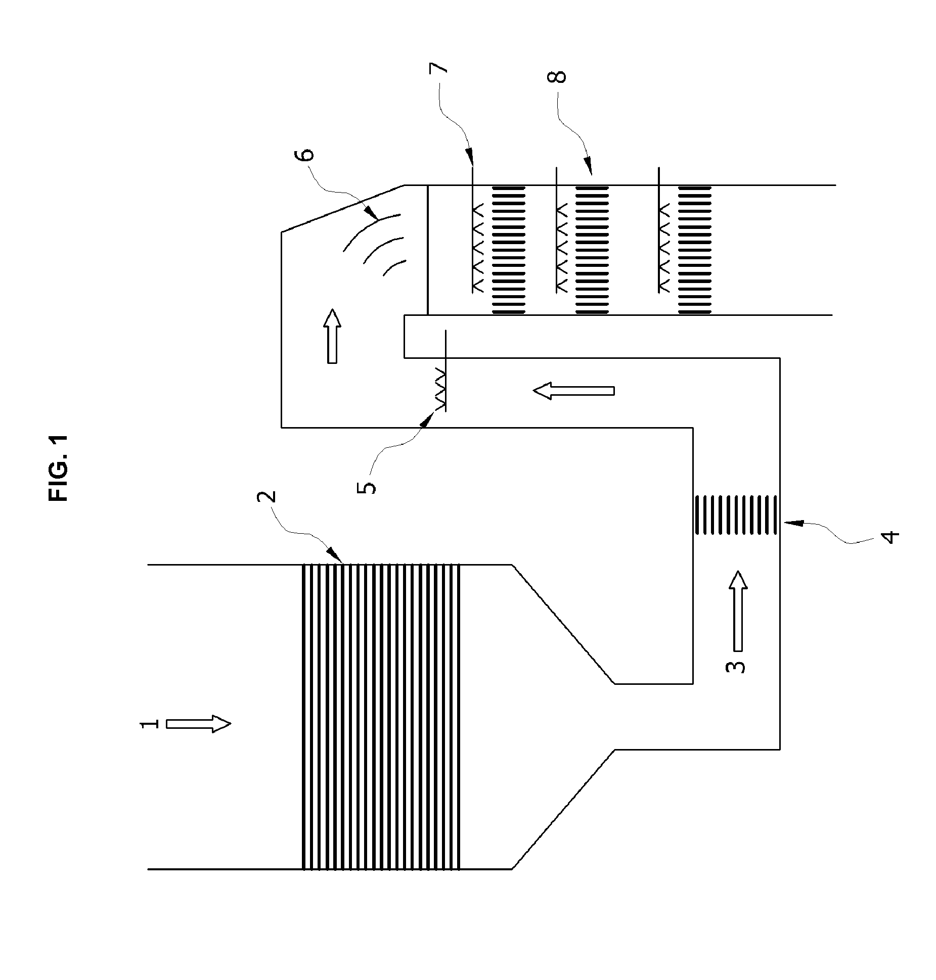
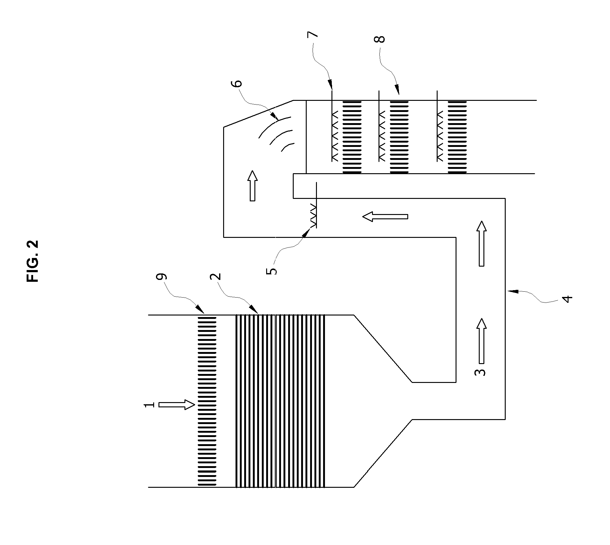
The present disclosure relates to a method for removing nitrogen oxides (NOx) more effectively at 300° C. or below in boilers, gas turbines, incinerators, diesel engines, glass melting furnaces, etc. by selective catalytic reduction (SCR).To this end, an oxidation catalyst is mounted in front of a NOx-reducing device based on selective catalytic reduction and the NOx composition, i.e. the ratio of NO:NO2, in the exhaust gas is adjusted to about 1:1, such that de-NOx catalytic reaction is carried out under optimized fast SCR condition and de-NOx efficiency at low temperature can be maximized.
Description
TECHNICAL FIELD[0001]The present disclosure relates to a method for removing nitrogen oxides (NOx) more effectively at 300° C. or below by adjusting the composition of the exhaust gas from boilers, gas turbines, incinerators, diesel engines, glass melting furnaces, etc. to be optimized for fast selective catalytic reduction (SCR).BACKGROUND ART[0002]Nitrogen oxides (NOx) emitted from power station boilers, gas turbines, industrial boilers, incinerators, diesel engines, or the like are a major cause of pollution.[0003]NOx is an important air pollutant produced during combustion of fuels. Although the term includes all nitrogen oxides such as N2O, NO, N2O3, NO2, N2O5, NO3, etc., it is used in the present disclosure to refer to NO and NO2, which are the main cause of air pollution.[0004]Methods for inhibiting or reducing NO production include low excess air firing, combustion zone cooling, combustion air preheating control, combustion device changing, staged combustion, water vapor spr...
Claims
Login to View More Application Information
Patent Timeline
 IPC IPC(8): B01D53/56
CPCB01D53/565B01D53/8625B01D2251/2062B01D2251/208B01D2258/012B01D2258/0241F23J15/003F23J2215/10F23J2219/10F23J2900/15004Y10T29/49826
InventorKIM, DAE WOOPARK, HA KUEJUNG, JAE PIL
OwnerGSCO